Menu operation (continued)
4. SINGAL menu
| Menu option | Setting | Feature description | ||
HORIZ. POSITION |
|
| Select this setting to adjust the horizontal position of projected images. | ||
|
|
|
|
|
|
VERT. POSITION |
|
| Select this setting to adjust the vertical position of projected images. | ||
|
|
|
|
|
|
FINE SYNC. |
|
| Select this setting to eliminate flickering or blurs, if they appear, when | ||
|
| you are viewing projected images. | |||
|
|
|
|
| |
|
|
|
|
|
|
TRACKING |
|
| Select this setting to eliminate vertical wide stripes, if they appear, when | ||
|
| you are viewing projected images. | |||
|
|
|
|
| |
|
|
|
|
|
|
|
| AUTO | Automatically sets the appropriate setting. | ||
|
|
|
|
|
|
|
| RGB | Select this setting when you connect the projector to high definition | ||
|
| video equipment having R, G, and B output terminals. | |||
COMPUTER INPUT |
|
|
| ||
|
|
|
| ||
|
|
| Select this setting when you connect the projector to a DVD player or | ||
|
|
|
|
| |
|
| YCBCR/YPBPR | other device having Y, CB, and CR (or Y, PB, and PR) component video | ||
|
|
|
|
| output terminals. |
|
|
|
|
|
|
OVER SCAN |
| Use this setting to adjust the display area of projected images. | |||
|
|
|
|
|
|
HOLD | OFF / ON |
|
| Use this setting to adjust projected images when flagging occurs in the | |
|
| upper area of the screen. | |||
|
|
|
|
| |
|
|
|
|
|
|
USER |
|
|
|
| |
|
|
|
|
|
|
| CLAMP POSITION |
|
| Use this setting to correct solid white or solid black that appears in pro- | |
|
|
| jected images | ||
|
|
|
|
| |
|
|
|
|
|
|
| CLAMP WIDTH |
|
| Use this setting to correct solid black that appears in projected images. | |
|
|
|
|
|
|
| VERT.SYNC | AUTO / OFF | Use this setting to adjust projected images when the motion is not | ||
| smooth. Select AUTO for most cases. | ||||
|
|
|
|
| |
|
|
|
|
|
|
| LPF | ON / OFF | Select this setting to enable or disable LPF. | ||
|
|
|
|
|
|
| SHUTTER(U) |
|
| Use this setting to adjust projected images when noise appears in the | |
|
|
| top part of the image. | ||
|
|
|
|
| |
|
|
|
|
|
|
| SHUTTER(L) |
|
| Use this setting to adjust projected images when noise appears in the | |
|
|
| bottom part of the image. | ||
|
|
|
|
| |
|
|
|
|
|
|
| SHUTTER(LS) |
|
| Use this setting to adjust projected images when noise appears in the | |
|
|
| left half of the image. | ||
|
|
|
|
| |
|
|
|
|
|
|
| SHUTTER(RS) |
|
| Use this setting to adjust projected images when noise appears in the | |
|
|
| right half of the image. | ||
|
|
|
|
| |
opt. |
| |
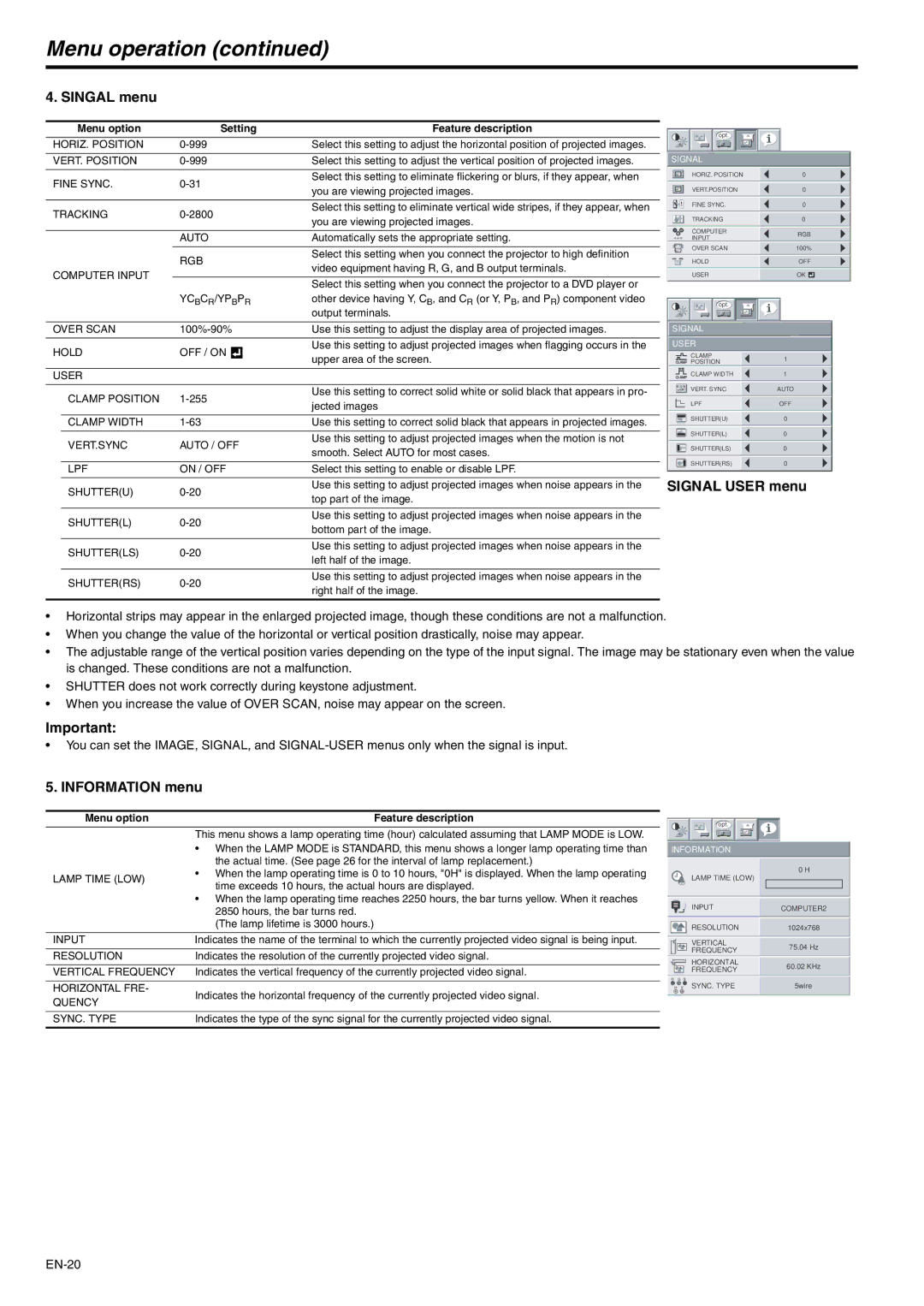
SIGNAL |
| |
HORIZ. POSITION | 0 | |
VERT.POSITION | 0 | |
FINE SYNC. | 0 | |
TRACKING | 0 | |
COMPUTER | RGB | |
RRGGBB INPUT | ||
| ||
OVER SCAN | 100% | |
HOLD | OFF | |
USER | OK | |
opt. |
| |
SIGNAL |
| |
USER |
|
|
|
| CLAMP | 1 |
|
|
| POSITION | |
|
|
|
|
|
|
|
| CLAMP WIDTH | 1 |
|
|
|
|
|
|
| VERT. SYNC | AUTO | |
|
|
|
|
|
|
|
| LPF | OFF |
|
|
|
|
|
SHUTTER(U)0
SHUTTER(L)0
SHUTTER(LS)0
SHUTTER(RS)0
SIGNAL USER menu
•Horizontal strips may appear in the enlarged projected image, though these conditions are not a malfunction.
•When you change the value of the horizontal or vertical position drastically, noise may appear.
•The adjustable range of the vertical position varies depending on the type of the input signal. The image may be stationary even when the value is changed. These conditions are not a malfunction.
•SHUTTER does not work correctly during keystone adjustment.
•When you increase the value of OVER SCAN, noise may appear on the screen.
Important:
•You can set the IMAGE, SIGNAL, and
5. INFORMATION menu
Menu option | Feature description | |
| This menu shows a lamp operating time (hour) calculated assuming that LAMP MODE is LOW. | |
| • When the LAMP MODE is STANDARD, this menu shows a longer lamp operating time than | |
| the actual time. (See page 26 for the interval of lamp replacement.) | |
LAMP TIME (LOW) | • When the lamp operating time is 0 to 10 hours, "0H" is displayed. When the lamp operating | |
time exceeds 10 hours, the actual hours are displayed. | ||
| ||
| • When the lamp operating time reaches 2250 hours, the bar turns yellow. When it reaches | |
| 2850 hours, the bar turns red. | |
| (The lamp lifetime is 3000 hours.) | |
|
| |
INPUT | Indicates the name of the terminal to which the currently projected video signal is being input. | |
|
| |
RESOLUTION | Indicates the resolution of the currently projected video signal. | |
|
| |
VERTICAL FREQUENCY | Indicates the vertical frequency of the currently projected video signal. | |
|
| |
HORIZONTAL FRE- | Indicates the horizontal frequency of the currently projected video signal. | |
QUENCY | ||
| ||
|
| |
SYNC. TYPE | Indicates the type of the sync signal for the currently projected video signal. | |
|
|
opt.
INFORMATION
0 H
LAMP TIME (LOW)
INPUTCOMPUTER2
| RESOLUTION | 1024x768 |
| VERTICAL | 75.04 Hz |
| FREQUENCY | |
|
| |
| HORIZONTAL | 60.02 KHz |
| FREQUENCY | |
|
| |
R G | B |
|
H V | SYNC. TYPE | 5wire |