Installation
Installation Requirements
Important:
•Installation shall comply with local electrical, health and safety requirements.
•It is most important that this oven is installed correctly and that oven operation is correct before use.
•If you have any questions regarding the proper installation and / or operation of this oven, please contact your local Turbofan distributor.
Unpacking
1.Remove all packaging and transit protection including all protective plastic coating from the exterior stainless steel panels.
2.Check the oven and supplied parts for damage. Report any damage immediately to the carrier and distributor.
3.Check that the following parts have been supplied with your oven:-
4 x Leg Adjustable.
4.Report any deficiencies to the distributor who supplied your oven.
5.Securely fit the 4 legs supplied with the oven.
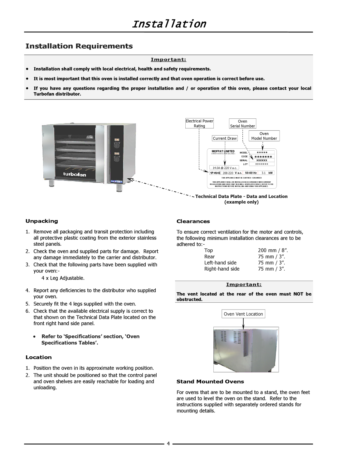
6.Check that the available electrical supply is correct to that shown on the Technical Data Plate located on the front right hand side panel.
•Refer to ‘Specifications’ section, ‘Oven Specifications Tables’.
Location
1.Position the oven in its approximate working position.
2.The unit should be positioned so that the control panel and oven shelves are easily reachable for loading and unloading.
Electrical Power |
|
|
|
|
|
| Oven |
|
|
|
|
|
|
|
|
|
| |||
Rating |
|
|
| Serial Number |
|
|
|
|
|
|
| |||||||||
|
|
|
|
|
|
|
|
|
|
|
|
|
|
|
|
|
|
|
|
|
|
|
|
|
|
|
|
|
|
|
|
|
|
|
| Oven | |||||
| Current Draw |
|
|
| Model Number | |||||||||||||||
|
|
|
|
|
|
|
|
|
|
|
|
|
|
|
|
|
|
|
|
|
| MOFFAT LIMITED |
|
|
|
|
|
|
|
|
|
|
|
|
|
|
| ||||
|
|
| MODEL |
|
|
| ***** |
|
|
| ||||||||||
| CHRISTCHURCH ( NEW ZEALAND ) |
|
|
|
|
|
|
| ||||||||||||
|
|
|
|
|
|
|
| CODE |
| ******* |
| |||||||||
|
|
|
|
|
|
|
| SERIAL |
|
| xxxxxx |
| ||||||||
|
|
|
|
|
|
|
|
| LOT |
| ******* |
|
|
| ||||||
| 14.0A @ 220 V a.c. |
|
|
|
|
|
|
|
|
|
|
|
|
| ||||||
|
|
|
|
|
|
|
|
|
|
|
|
|
|
|
|
|
|
|
|
|
| 1P+N+E |
|
| V a.c. |
|
| 13.51 | kW |
| |||||||||||
|
|
|
|
|
|
|
|
|
|
|
|
|
|
|
|
|
|
|
|
|
THIS APPLIANCE MUST BE EARTHED / GROUNDED
THIS APPLIANCE SHALL BE INSTALLED IN ACCORDANCE WITH CURRENT
REGULATIONS AND USED ONLY IN A
INSTRUCTIONS BEFORE INSTALLING AND USING THIS APPLIANCE.
Technical Data Plate - Data and Location
(example only)
Clearances
To ensure correct ventilation for the motor and controls, the following minimum installation clearances are to be adhered to:-
Top | 200 mm / 8”. |
Rear | 75 mm / 3”. |
75 mm / 3”. | |
75 mm / 3”. |
Important:
The vent located at the rear of the oven must NOT be obstructed.
Oven Vent Location
Stand Mounted Ovens
For ovens that are to be mounted to a stand, the oven feet are used to level the oven on the stand. Refer to the instructions supplied with separately ordered stands for mounting details.
4
