GAS LINE AND ELECTRICAL INSTALLATION
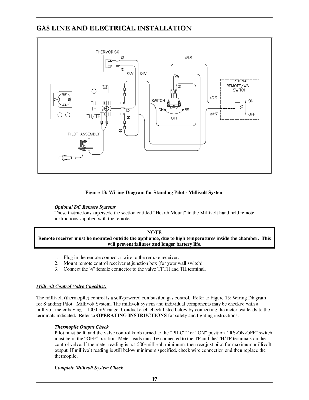
Figure 13: Wiring Diagram for Standing Pilot - Millivolt System
Optional DC Remote Systems
These instructions supersede the section entitled “Hearth Mount” in the Millivolt hand held remote instructions supplied with the remote.
NOTE
Remote receiver must be mounted outside the appliance, due to high temperatures inside the chamber. This
will prevent failures and longer battery life.
1.Plug in the remote connector wire to the remote receiver.
2.Mount remote control receiver at junction box (for your wall switch)
3.Connect the ¼” female connector to the valve TPTH and TH terminal.
Millivolt Control Valve Checklist:
The millivolt (thermopile) control is a
Thermopile Output Check
Pilot must be lit and the valve control knob turned to the “PILOT” or “ON” position.
Complete Millivolt System Check
17