ELECTRICAL WIRING (Millivolt)
Connecting Remote Receiver
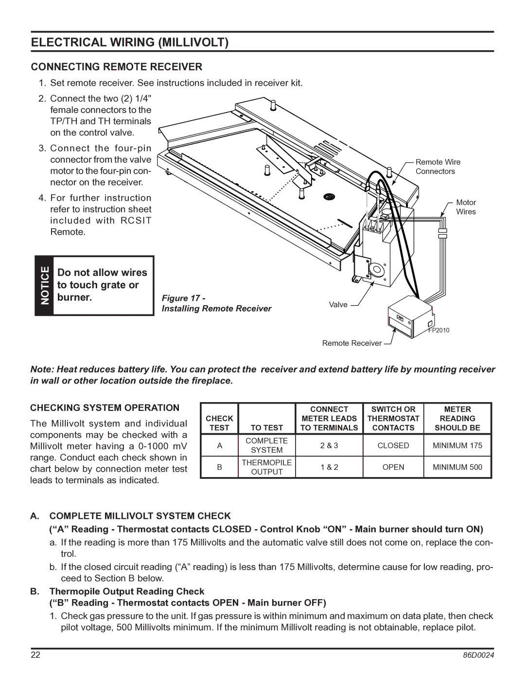
1. Set remote receiver. See instructions included in receiver kit.
2.Connect the two (2) 1/4" female connectors to the TP/TH and TH terminals on the control valve.
3.Connect the
4.For further instruction refer to instruction sheet included with RCSIT Remote.
| NOTICE | Do not allow wires |
| burner. | |
|
| to touch grate or |
|
|
|
Figure 17 -
Installing Remote Receiver
Remote Wire
Connectors
Motor
Wires
Valve ![]()
FP2010
Remote Receiver
Note: Heat reduces battery life. You can protect the receiver and extend battery life by mounting receiver in wall or other location outside the fireplace.
Checking System Operation
The Millivolt system and individual components may be checked with a Millivolt meter having a
|
| CONNECT | SWITCH OR | METER | |
CHECK |
| METER LEADS | THERMOSTAT | READING | |
TEST | TO TEST | TO TERMINALS | CONTACTS | SHOULD BE | |
A | COMPLETE | 2 & 3 | CLOSED | MINIMUM 175 | |
SYSTEM | |||||
|
|
|
| ||
B | THERMOPILE | 1 & 2 | OPEN | MINIMUM 500 | |
OUTPUT | |||||
|
|
|
|
A.Complete Millivolt System Check
(“A” Reading - Thermostat contacts CLOSED - Control Knob “ON” - Main burner should turn ON)
a.If the reading is more than 175 Millivolts and the automatic valve still does not come on, replace the con- trol.
b.If the closed circuit reading (“A” reading) is less than 175 Millivolts, determine cause for low reading, pro- ceed to Section B below.
B.Thermopile Output Reading Check
(“B” Reading - Thermostat contacts OPEN - Main burner OFF)
1. Check gas pressure to the unit. If gas pressure is within minimum and maximum on data plate, then check pilot voltage, 500 Millivolts minimum. If the minimum Millivolt reading is not obtainable, replace pilot.
22 | 86D0024 |