ELECTRICAL WIRING (MILLI-VOLT)
CONNECTING REMOTE RECEIVER
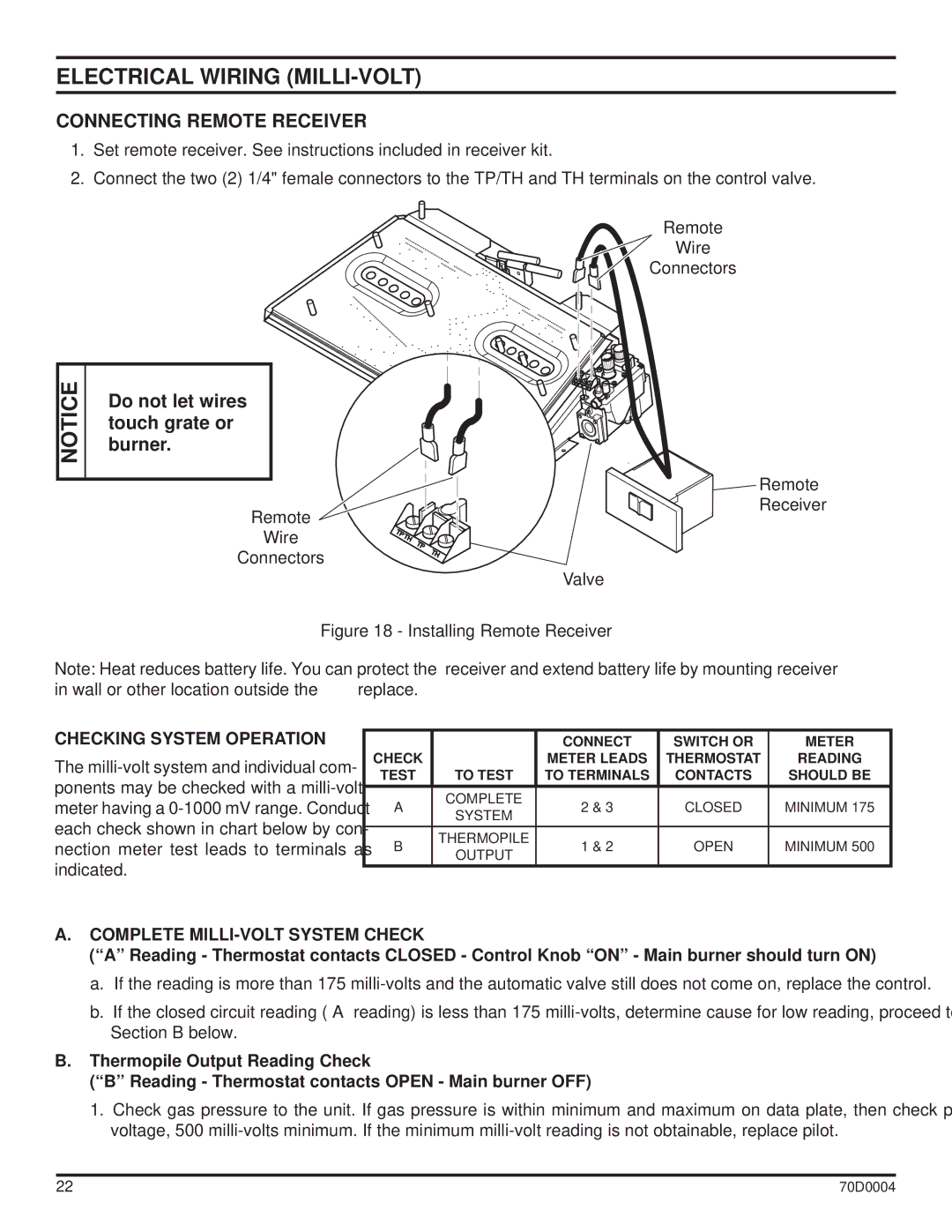
1.Set remote receiver. See instructions included in receiver kit.
2.Connect the two (2) 1/4" female connectors to the TP/TH and TH terminals on the control valve.
Remote
Wire
Connectors
|
|
|
NOTICE |
| Do not let wires |
|
| |
|
| touch grate or |
|
| burner. |
|
|
|
|
|
|
Remote
Wire
Connectors
Valve
Remote Receiver
Figure 18 - Installing Remote Receiver
Note: Heat reduces battery life. You can protect the receiver and extend battery life by mounting receiver in wall or other location outside the fireplace.
CHECKING SYSTEM OPERATION
The
|
| CONNECT | SWITCH OR | METER | |
CHECK |
| METER LEADS | THERMOSTAT | READING | |
TEST | TO TEST | TO TERMINALS | CONTACTS | SHOULD BE | |
A | COMPLETE | 2 & 3 | CLOSED | MINIMUM 175 | |
SYSTEM | |||||
|
|
|
| ||
B | THERMOPILE | 1 & 2 | OPEN | MINIMUM 500 | |
OUTPUT | |||||
|
|
|
|
A.COMPLETE MILLI-VOLT SYSTEM CHECK
(“A” Reading - Thermostat contacts CLOSED - Control Knob “ON” - Main burner should turn ON)
a.If the reading is more than 175
b.If the closed circuit reading (“A” reading) is less than 175
B.Thermopile Output Reading Check
(“B” Reading - Thermostat contacts OPEN - Main burner OFF)
1. Check gas pressure to the unit. If gas pressure is within minimum and maximum on data plate, then check pilot voltage, 500
22 | 70D0004 |
