MCU_PORT
The MCU_PORT provides access to the peripheral features and I/O lines of the HC12 as follows:
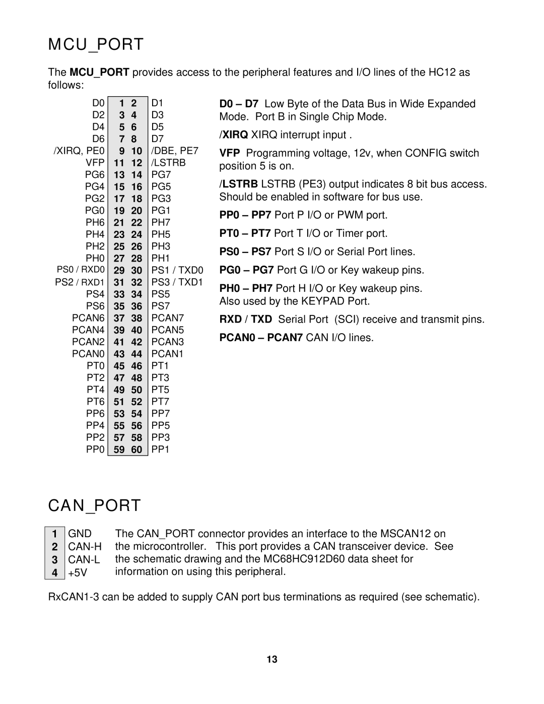
D0
D2
D4
D6 /XIRQ, PE0
VFP
PG6
PG4
PG2
PG0
PH6
PH4
PH2
PH0
PS0 / RXD0 PS2 / RXD1
PS4
PS6
PCAN6
PCAN4
PCAN2
PCAN0
PT0
PT2
PT4
PT6
PP6
PP4
PP2
PP0
12
34
56
78
910
1112
1314
1516
1718
1920
2122
2324
2526
2728
2930
3132
3334
3536
3738
3940
4142
4344
4546
4748
4950
5152
5354
5556
5758
5960
D1
D3
D5
D7
/DBE, PE7
/LSTRB
PG7
PG5
PG3
PG1
PH7
PH5
PH3
PH1
PS1 / TXD0 PS3 / TXD1 PS5
PS7
PCAN7
PCAN5
PCAN3
PCAN1
PT1
PT3
PT5
PT7
PP7
PP5
PP3
PP1
D0 – D7 Low Byte of the Data Bus in Wide Expanded Mode. Port B in Single Chip Mode.
/XIRQ XIRQ interrupt input .
VFP Programming voltage, 12v, when CONFIG switch position 5 is on.
/LSTRB LSTRB (PE3) output indicates 8 bit bus access. Should be enabled in software for bus use.
PP0 – PP7 Port P I/O or PWM port.
PT0 – PT7 Port T I/O or Timer port.
PS0 – PS7 Port S I/O or Serial Port lines. PG0 – PG7 Port G I/O or Key wakeup pins.
PH0 – PH7 Port H I/O or Key wakeup pins. Also used by the KEYPAD Port.
RXD / TXD Serial Port (SCI) receive and transmit pins.
PCAN0 – PCAN7 CAN I/O lines.
CAN_PORT
1GND
2CAN-H
3CAN-L
4+5V
The CAN_PORT connector provides an interface to the MSCAN12 on the microcontroller. This port provides a CAN transceiver device. See the schematic drawing and the MC68HC912D60 data sheet for information on using this peripheral.
13