CONFIG SWITCH
The
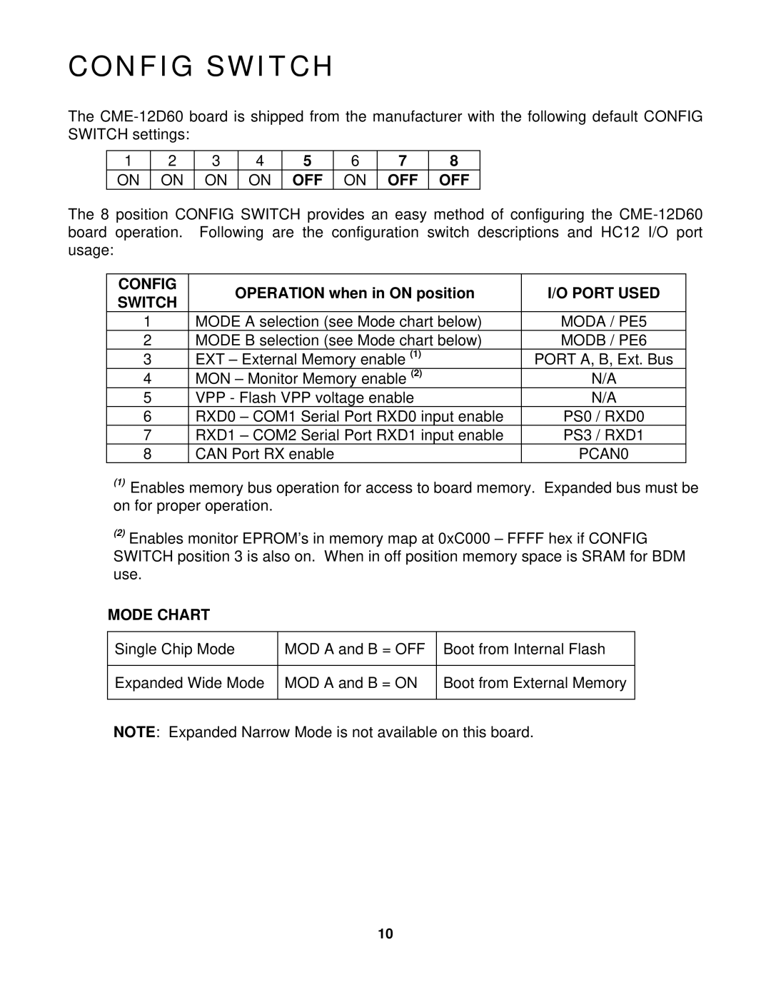
1 | 2 | 3 | 4 | 5 | 6 | 7 | 8 |
ON | ON | ON | ON | OFF | ON | OFF | OFF |
The 8 position CONFIG SWITCH provides an easy method of configuring the
CONFIG | OPERATION when in ON position | I/O PORT USED | |
SWITCH | |||
|
| ||
1 | MODE A selection (see Mode chart below) | MODA / PE5 | |
2 | MODE B selection (see Mode chart below) | MODB / PE6 | |
3 | EXT – External Memory enable (1) | PORT A, B, Ext. Bus | |
4 | MON – Monitor Memory enable (2) | N/A | |
5 | VPP - Flash VPP voltage enable | N/A | |
6 | RXD0 – COM1 Serial Port RXD0 input enable | PS0 / RXD0 | |
7 | RXD1 – COM2 Serial Port RXD1 input enable | PS3 / RXD1 | |
8 | CAN Port RX enable | PCAN0 |
(1)Enables memory bus operation for access to board memory. Expanded bus must be on for proper operation.
(2)Enables monitor EPROM’s in memory map at 0xC000 – FFFF hex if CONFIG SWITCH position 3 is also on. When in off position memory space is SRAM for BDM use.
MODE CHART
Single Chip Mode | MOD A and B = OFF | Boot from Internal Flash |
|
|
|
Expanded Wide Mode | MOD A and B = ON | Boot from External Memory |
|
|
|
NOTE: Expanded Narrow Mode is not available on this board.
10