COM1
TXD0
RXD0
GND
1
26
37
48
59
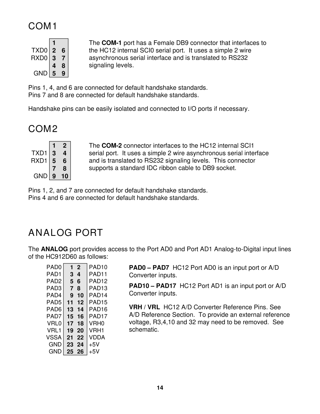
The
Pins 1, 4, and 6 are connected for default handshake standards. Pins 7 and 8 are connected for default handshake standards.
Handshake pins can be easily isolated and connected to I/O ports if necessary.
COM2
TXD1
RXD1
GND
12
34
56
78
910
The
Pins 1, 2, and 7 are connected for default handshake standards.
Pins 4 and 6 are connected for default handshake standards.
ANALOG PORT
The ANALOG port provides access to the Port AD0 and Port AD1
PAD0
PAD1
PAD2
PAD3
PAD4
PAD5
PAD6
PAD7
VRL0
VRL1
VSSA GND GND
1 2 PAD10
3 4 PAD11
5 6 PAD12
7 8 PAD13
9 10 PAD14
11 12 PAD15
13 14 PAD16
15 16 PAD17
17 18 VRH0
19 20 VRH1
21 22 VDDA
23 24 +5V
25 26 +5V
PAD0 – PAD7 HC12 Port AD0 is an input port or A/D Converter inputs.
PAD10 – PAD17 HC12 Port AD1 is an input port or A/D Converter inputs.
VRH / VRL HC12 A/D Converter Reference Pins. See A/D Reference Section. To provide an external reference voltage, R3,4,10 and 32 may need to be removed. See schematic.
14
