PORTS AND CONNECTORS
LCD_PORT
The LCD_PORT interface is connected to the data bus and memory mapped to locations BF0
–BFF hex assigned to CS7. For the standard display, address BF0 is the Command register, address BF1 is the Data register.
The interface supports all OPTREX™ DMC series displays in 8 bit bus mode with up to 80 characters and provides the most common pinout for a dual row rear mounted display connector. Power, ground, and Vee are also available at this connector.
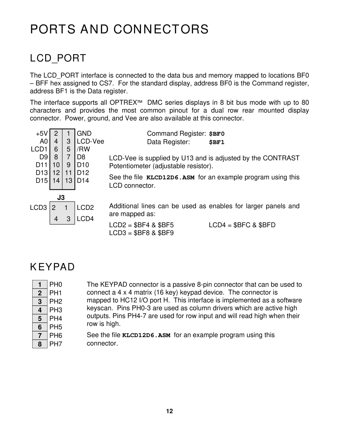
+5V | 2 | 1 | GND |
A0 | 4 | 3 | |
LCD1 | 6 | 5 | /RW |
D9 | 8 | 7 | D8 |
D11 | 10 | 9 | D10 |
D13 | 12 | 11 | D12 |
D15 | 14 | 13 | D14 |
|
|
|
|
Command Register: $BF0
Data Register: | $BF1 |
See the file KLCD12D6.ASM for an example program using this LCD connector.
| J3 | |
LCD3 | 2 | 1 |
| 4 | 3 |
LCD2
LCD4
Additional lines can be used as enables for larger panels and are mapped as:
LCD2 = $BF4 & $BF5 | LCD4 = $BFC & $BFD |
LCD3 = $BF8 & $BF9 |
|
KEYPAD
1PH0
2PH1
3PH2
4PH3
5PH4
6PH5
7PH6
8PH7
The KEYPAD connector is a passive
See the file KLCD12D6.ASM for an example program using this connector.
12