RECORDING YOUR CONNECTIONS
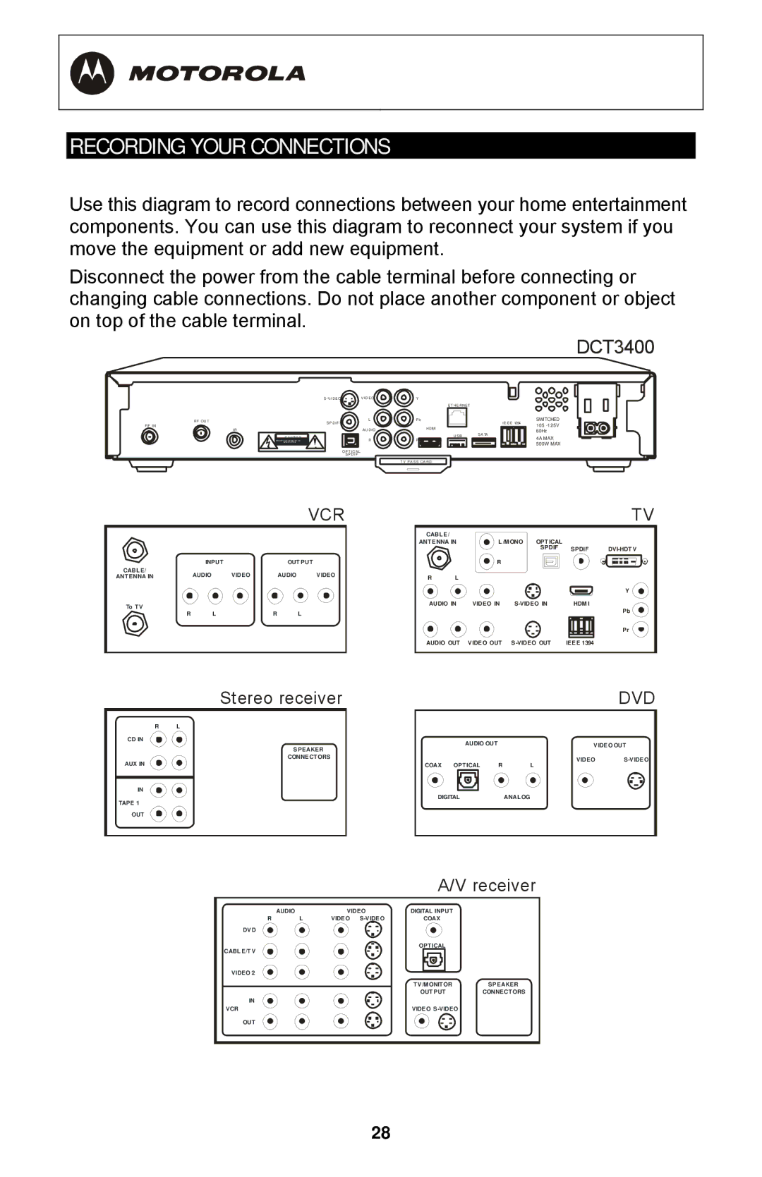
Use this diagram to record connections between your home entertainment components. You can use this diagram to reconnect your system if you move the equipment or add new equipment.
Disconnect the power from the cable terminal before connecting or changing cable connections. Do not place another component or object on top of the cable terminal.
DCT3400
RF OUT
RF IN
S | VIDEO |
SPDIF | L |
| |
IR | AUDIO |
C A U TI O N | R |
| |
| OPT ICAL |
| SPDIF |
Y
Pb
HDMI
Pr |
T V PASS CARD
ET HERNET
IEEE 1394
USB SATA
SWITCHED
105
4A MAX
500W MAX
|
|
|
| VCR |
|
|
|
|
|
| TV |
|
|
|
|
| CABLE/ |
| L /M ONO | OPTICAL |
|
| |
|
|
|
|
| ANTENNA IN |
|
| ||||
|
|
|
|
|
|
|
|
| SPDIF | SPDIF | |
| INPUT |
| OUT PUT |
|
| R |
|
|
|
| |
CABLE/ | AUDIO | VIDEO | AUDIO | VIDEO |
|
|
|
|
|
|
|
ANTENNA IN | R | L |
|
|
|
|
| ||||
|
|
|
|
|
|
|
|
|
|
| Y |
To T V |
|
|
|
| AUDIO IN | VIDEO IN | HDM I | Pb | |||
|
|
|
|
|
|
|
|
|
| ||
R | L |
| R | L |
|
|
|
|
|
| |
|
|
|
|
|
|
|
| ||||
|
|
|
|
|
|
|
|
|
|
| Pr |
|
|
|
|
| AUDIO OUT | VIDEO OUT | IEEE 1394 |
| |||
| Stereo receiver |
| DVD |
R | L |
|
|
CD IN | AUDIO OUT | VIDEO OUT | |
| |||
| SPEAKER |
|
|
AUX IN | CONNECT ORS | VIDEO | |
COAX OPTICAL R | L |
| |
IN | DIGITAL | ANAL OG |
|
|
| ||
TAPE 1
OUT
|
|
| A/V receiver | |
| AUDIO | VIDEO | DIGITAL INPUT |
|
R | L | VIDEO | COAX |
|
DVD |
|
|
|
|
CABLE/T V |
|
| OPTICAL |
|
|
|
|
| |
VIDEO 2 |
|
|
|
|
|
|
| TV/M ONITOR | SPEAKER |
|
|
| OUT PUT | CONNECT ORS |
IN |
|
|
|
|
VCR |
|
| VIDEO |
|
OUT
28