C M L 1 2 S D P 2 5 6 | 0 7 / 1 7 / 0 2 |
CAN BUS TERMINATION
The CAN port provides RC11,12, and 13 1206 SMT size termination resistors on the bottom of the CML12Sxxx board that are not installed at the factory. The termination resistors provide optional bias and termination impedance for the CAN bus connected to the CAN Port. Type of wire media, data rate, length of wire, and number of CAN bus nodes can all effect the requirement or value of the termination for the CAN bus. User should refer to particular application for termination requirements.
RC11
RC12
RC13 CAN Termination Resistor: Provides end point termination between
L signal.
P1 - P4 HCS12 Header Ring
P1 - P4 provide a header ring for all I/O of the HCS12 device. These connectors are not installed. User should refer to the CML12S board schematic diagram for connector pin connections. All HCS12 I/O is available from the other I/O Ports on the board.
LCD_PORT
The LCD_PORT interface is connected to the HCS12
The interface supports all OPTREX™ DMC series and similar displays with up to 80 characters in 4 bit bus mode and provides the most common pinout for a dual row rear mounted display connector. The LCD module VEE or contrast potential is 0 Volts on this board. The LCD module type should be TN (Standard Twist) style and Reflective to support this VEE potential. The Axiom Mfg.
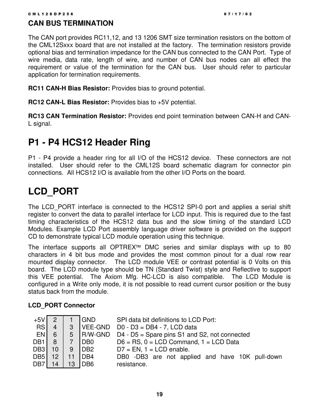
LCD_PORT Connector |
|
|
| |||
|
|
|
|
| ||
+5V | 2 | 1 | GND | SPI data bit definitions to LCD Port: | ||
RS | 4 | 3 | D0 | - D3 | = DB4 - 7, LCD data | |
EN | 6 | 5 | D4 | - D5 | = Spare pins S1 and S2, not connected | |
DB1 | 8 | 7 | DB0 | D6 | = RS, 0 = LCD Command, 1 = LCD Data | |
DB3 | 10 | 9 | DB2 | D7 | = EN, 1 = LCD enable. | |
DB5 | 12 | 11 | DB4 | DB0 | ||
DB7 | 14 | 13 | DB6 | resistance. | ||
19