Chapter 6 Interfaces
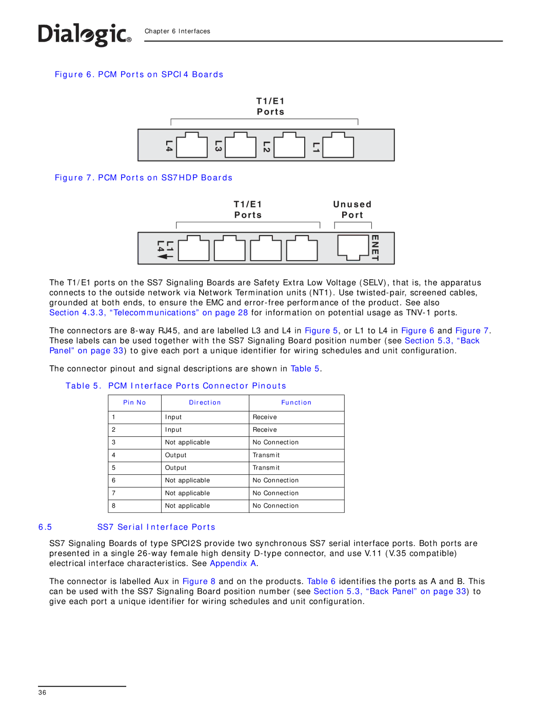
Figure 6. PCM Ports on SPCI4 Boards
T 1 / E 1
P o r t s
L 4 |
|
|
| L 3 |
|
|
| ||
|
|
|
|
|
L 2 |
|
|
| L 1 |
|
|
| ||
|
|
|
|
|
Figure 7. PCM Ports on SS7HDP Boards
T 1 / E 1 | U n u s e d | |
P o r t s |
| P o r t |
|
|
|
|
|
|
L 1 L 4
![]() E N E T
E N E T
The T1/E1 ports on the SS7 Signaling Boards are Safety Extra Low Voltage (SELV), that is, the apparatus connects to the outside network via Network Termination units (NT1). Use
The connectors are
The connector pinout and signal descriptions are shown in Table 5.
Table 5. PCM Interface Ports Connector Pinouts
Pin No | Direction | Function |
|
|
|
1 | Input | Receive |
|
|
|
2 | Input | Receive |
|
|
|
3 | Not applicable | No Connection |
|
|
|
4 | Output | Transmit |
|
|
|
5 | Output | Transmit |
|
|
|
6 | Not applicable | No Connection |
|
|
|
7 | Not applicable | No Connection |
|
|
|
8 | Not applicable | No Connection |
|
|
|
6.5SS7 Serial Interface Ports
SS7 Signaling Boards of type SPCI2S provide two synchronous SS7 serial interface ports. Both ports are presented in a single
The connector is labelled Aux in Figure 8 and on the products. Table 6 identifies the ports as A and B. This can be used with the SS7 Signaling Board position number (see Section 5.3, “Back Panel” on page 33) to give each port a unique identifier for wiring schedules and unit configuration.
36