Dialogic® SS7G21 and SS7G22 Signaling Servers Hardware Manual Issue 7
Chapter 6: Interfaces
This section provides connector pinout details for all used interface connectors on the SS7G21 and SS7G22. For locations refer to Section 5.3, “Back Panel” on page 33.
6.1DC Power Input Terminal Block
A DC Power Input Terminal Block is provided at the rear of the
6.2Safety Ground Studs for Earthing
Two
6.3AC Power Input
Two AC power input connectors, type IEC320, are provided at the rear of the Power Supply Cage of AC powered product. Each connector supplies input power to one of the two Power Supply Module positions, refer to Section 5.3, “Back Panel” on page 33 for details. These connectors provide the safety ground connections for the product.
When selecting a suitable power cord(s) for connection to the AC power input(s), ensure that the cords comply with the AC POWER CORD warning provided in Chapter 1, “Warnings and Cautions”.
When selecting a suitable AC power outlet(s) for connection of the other end of the power cord(s), ensure that the outlet is earthed, and that it complies with the IF AC POWER SUPPLIES ARE INSTALLED warning in Chapter 1, “Warnings and Cautions” which covers the following aspects; mains AC power disconnect, grounding the rack installation, and overcurrent protection.
When in doubt, consult a qualified service tecnhician.
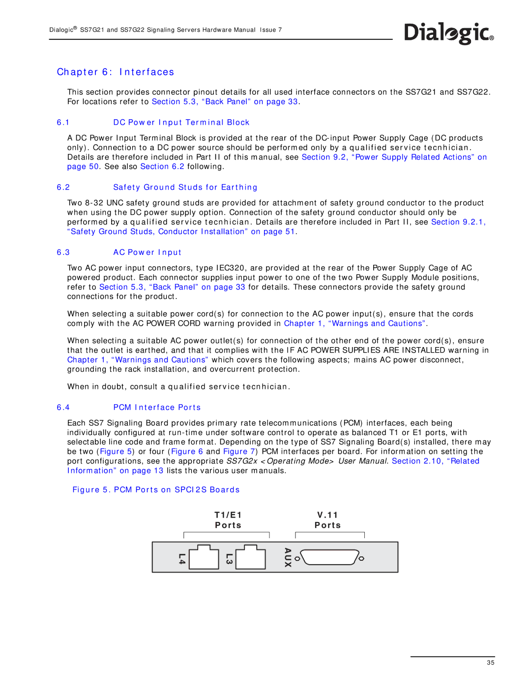
6.4PCM Interface Ports
Each SS7 Signaling Board provides primary rate telecommunications (PCM) interfaces, each being individually configured at
Figure 5. PCM Ports on SPCI2S Boards
T 1 / E 1 |
| V . 1 1 |
P o r t s |
| P o r t s |
|
|
|
|
|
|
L 4 |
L 3 | A U X |
35