Chapter 5 Hardware Description
5.2Front Panel
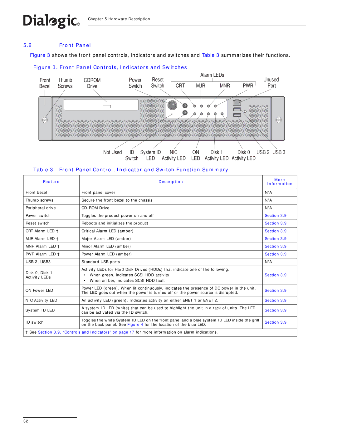
Figure 3 shows the front panel controls, indicators and switches and Table 3 summarizes their functions.
Figure 3. Front Panel Controls, Indicators and Switches
Front | Thumb | CDROM | Power | Reset |
|
| Alarm LEDs |
| Unused | |||
|
|
|
|
| ||||||||
Bezel | Screws | Drive | Switch | Switch | CRT | MJR | MNR | PWR | Port | |||
|
| Not Used | ID | System ID |
| NIC | ON |
| Disk 1 | Disk 0 | USB 2 USB 3 | |
|
|
| Switch |
| LED | Activity LED | LED | Activity LED | Activity LED |
| ||
Table 3. Front Panel Control, Indicator and Switch Function Summary
Feature | Description | More | |
Information | |||
|
| ||
|
|
| |
Front bezel | Front panel cover | N/A | |
|
|
| |
Thumb screws | Secure the front bezel to the chassis | N/A | |
|
|
| |
Peripheral drive | N/A | ||
|
|
| |
Power switch | Toggles the product power on and off | Section 3.9 | |
|
|
| |
Reset switch | Reboots and initializes the product | Section 3.9 | |
|
|
| |
CRT Alarm LED † | Critical Alarm LED (amber) | Section 3.9 | |
|
|
| |
MJR Alarm LED † | Major Alarm LED (amber) | Section 3.9 | |
|
|
| |
MNR Alarm LED † | Minor Alarm LED (amber) | Section 3.9 | |
|
|
| |
PWR Alarm LED † | Power Alarm LED (amber) | Section 3.9 | |
|
|
| |
USB 2, USB3 | Standard USB ports | N/A | |
|
|
| |
Disk 0, Disk 1 | Activity LEDs for Hard Disk Drives (HDDs) that indicate one of the following: |
| |
• When green, indicates SCSI HDD activity | Section 3.9 | ||
Activity LEDs | |||
• When amber, indicates SCSI HDD fault |
| ||
|
| ||
|
|
| |
ON Power LED | Power LED (green). When lit continuously, indicates the presence of DC power in the unit. | Section 3.9 | |
The LED goes out when the power is turned off or the power source is disrupted. | |||
|
| ||
|
|
| |
NIC Activity LED | An activity LED (green). Indicates activity on either ENET 1 or ENET 2. | Section 3.9 | |
|
|
| |
System ID LED | A system ID LED (white) that can be used to highlight the unit in a rack of units. The LED | Section 3.9 | |
can be activated via the ID switch. | |||
|
| ||
|
|
| |
ID switch | Toggles the white System ID LED on the front panel and a blue system ID LED inside the grill | Section 3.9 | |
on the back panel. See Figure 4 for the location of the blue LED. | |||
|
| ||
|
|
| |
† See Section 3.9, “Controls and Indicators” on page 17 for more information on alarm indications. |
| ||
|
|
| |
32
