Chapter 6 Interfaces
An SS7 Serial Interface Port Splitter Cable is available, DKL26 (see Chapter 12, “Part Number Reference”). This is a cable that converts from the dual V.11
Table 7. SS7 Serial Interface Port Splitter Cable
Pin No | Direction |
| Function |
|
|
| |
1 |
| Chassis ground | |
|
|
|
|
2 | Output | V.11 | Transmit true data |
|
|
| |
3 |
| No connection | |
|
|
|
|
4 | Input | V.11 | Receive true data |
|
|
| |
5 |
| No connection | |
|
|
|
|
6 | Input | V.11 | Receive true clock |
|
|
|
|
7 | Output | V.11 | Transmit true clock |
|
|
| |
8 |
| Signal Ground | |
|
|
|
|
9 | Output | V.11 | Transmit inverted data |
|
|
| |
10 |
| No connection | |
|
|
|
|
11 | Input | V.11 | Receive inverted data |
|
|
| |
12 |
| No connection | |
|
|
|
|
13 | Input | V.11 | Receive inverted clock |
|
|
|
|
14 | Output | V.11 | Transmit inverted clock |
|
|
| |
15 |
| No connection | |
|
|
|
|
6.6Ethernet Interfaces
To ensure EMC product regulation compliance for
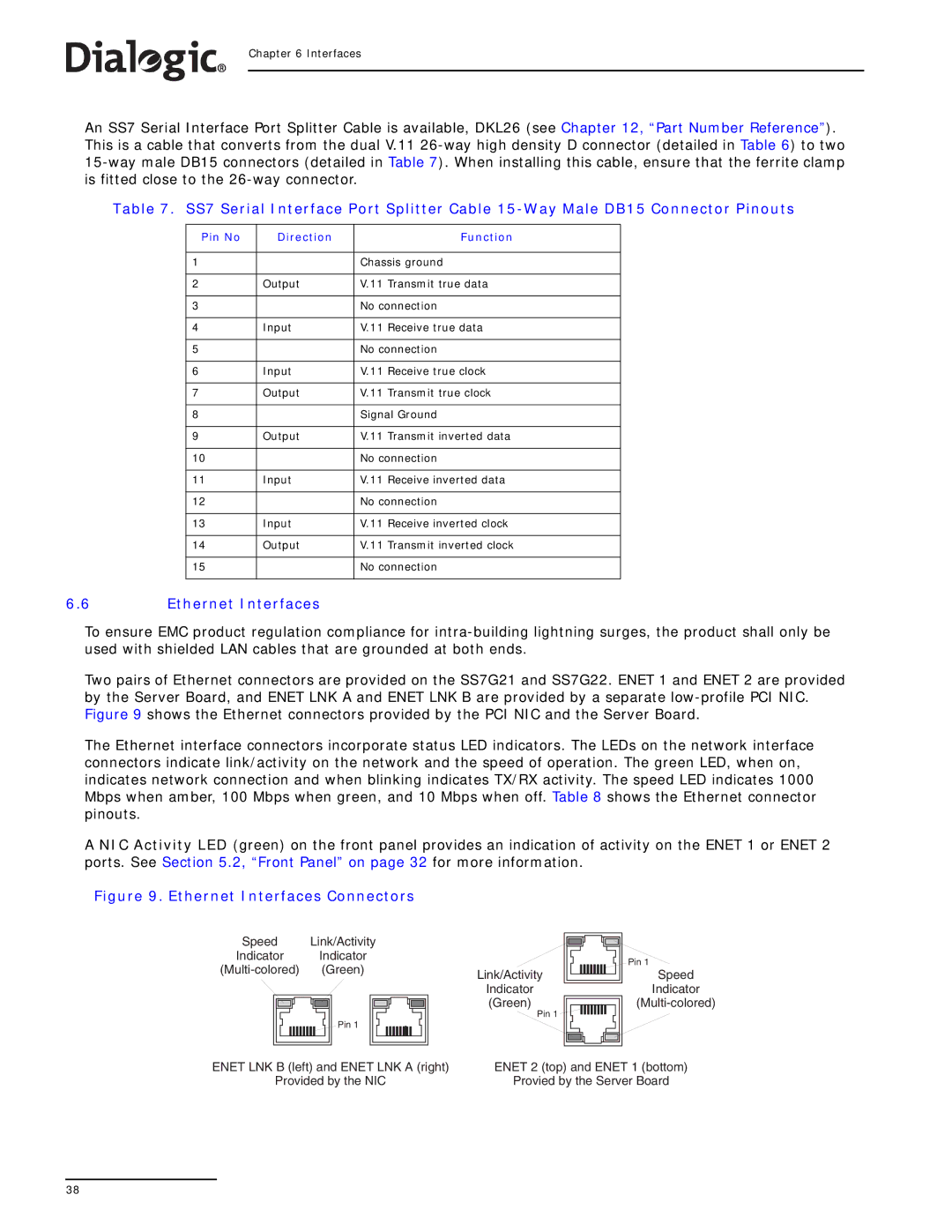
Two pairs of Ethernet connectors are provided on the SS7G21 and SS7G22. ENET 1 and ENET 2 are provided by the Server Board, and ENET LNK A and ENET LNK B are provided by a separate
The Ethernet interface connectors incorporate status LED indicators. The LEDs on the network interface connectors indicate link/activity on the network and the speed of operation. The green LED, when on, indicates network connection and when blinking indicates TX/RX activity. The speed LED indicates 1000 Mbps when amber, 100 Mbps when green, and 10 Mbps when off. Table 8 shows the Ethernet connector pinouts.
A NIC Activity LED (green) on the front panel provides an indication of activity on the ENET 1 or ENET 2 ports. See Section 5.2, “Front Panel” on page 32 for more information.
Figure 9. Ethernet Interfaces Connectors
Speed Link/Activity
Indicator Indicator
Pin 1
Link/Activity
Indicator
(Green)
Pin 1 ![]()
![]()
![]()
![]()
![]()
![]()
![]()
![]()
Pin 1
Speed
Indicator
ENET LNK B (left) and ENET LNK A (right) | ENET 2 (top) and ENET 1 (bottom) |
Provided by the NIC | Provied by the Server Board |
38