Dialogic® SS7G21 and SS7G22 Signaling Servers Hardware Manual Issue 7
5.3Back Panel
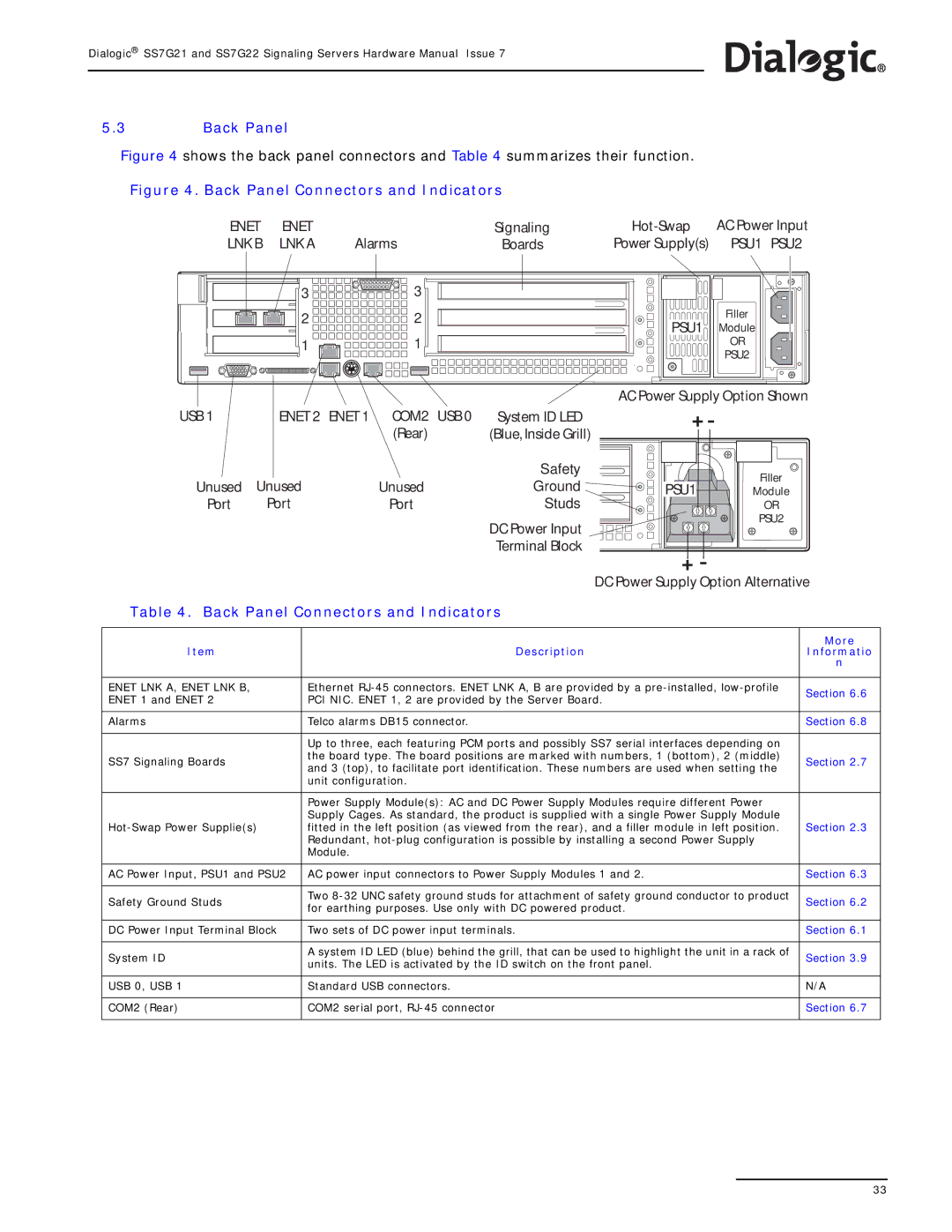
Figure 4 shows the back panel connectors and Table 4 summarizes their function.
Figure 4. Back Panel Connectors and Indicators
ENET | ENET |
| Signaling | AC Power Input | |
LNK B | LNK A | Alarms | Boards | Power Supply(s) | PSU1 PSU2 |
| 3 |
| 3 |
|
|
|
|
| 2 |
| 2 |
|
| PSU1 | Filler |
|
|
|
| Module | |||
|
|
|
|
|
| ||
| 1 |
| 1 |
|
|
| OR |
|
|
|
|
|
|
| PSU2 |
|
|
|
|
|
| AC Power Supply Option Shown | |
USB 1 | ENET 2 | ENET 1 | COM2 | USB 0 | System ID LED |
|
|
|
|
| (Rear) |
| (Blue, Inside Grill) |
|
|
|
|
|
|
| Safety |
| Filler |
Unused | Unused |
| Unused |
| Ground | PSU1 | |
|
| Module | |||||
Port | Port |
| Port |
| Studs |
| OR |
|
|
|
|
| DC Power Input |
| PSU2 |
|
|
|
|
|
|
| |
|
|
|
|
| Terminal Block |
|
|
| DC Power Supply Option Alternative | ||
Table 4. Back Panel Connectors and Indicators |
| ||
|
|
| |
|
| More | |
Item | Description | Informatio | |
|
| n | |
|
|
| |
ENET LNK A, ENET LNK B, | Ethernet | Section 6.6 | |
ENET 1 and ENET 2 | PCI NIC. ENET 1, 2 are provided by the Server Board. | ||
| |||
|
|
| |
Alarms | Telco alarms DB15 connector. | Section 6.8 | |
|
|
| |
| Up to three, each featuring PCM ports and possibly SS7 serial interfaces depending on |
| |
SS7 Signaling Boards | the board type. The board positions are marked with numbers, 1 (bottom), 2 (middle) | Section 2.7 | |
and 3 (top), to facilitate port identification. These numbers are used when setting the | |||
|
| ||
| unit configuration. |
| |
|
|
| |
| Power Supply Module(s): AC and DC Power Supply Modules require different Power |
| |
| Supply Cages. As standard, the product is supplied with a single Power Supply Module |
| |
fitted in the left position (as viewed from the rear), and a filler module in left position. | Section 2.3 | ||
| Redundant, |
| |
| Module. |
| |
|
|
| |
AC Power Input, PSU1 and PSU2 | AC power input connectors to Power Supply Modules 1 and 2. | Section 6.3 | |
|
|
| |
Safety Ground Studs | Two | Section 6.2 | |
for earthing purposes. Use only with DC powered product. | |||
|
| ||
|
|
| |
DC Power Input Terminal Block | Two sets of DC power input terminals. | Section 6.1 | |
|
|
| |
System ID | A system ID LED (blue) behind the grill, that can be used to highlight the unit in a rack of | Section 3.9 | |
units. The LED is activated by the ID switch on the front panel. | |||
|
| ||
|
|
| |
USB 0, USB 1 | Standard USB connectors. | N/A | |
|
|
| |
COM2 (Rear) | COM2 serial port, | Section 6.7 | |
|
|
| |
33