Getting Started
FV1:
 Voltage Checkpoints Connector (optional)
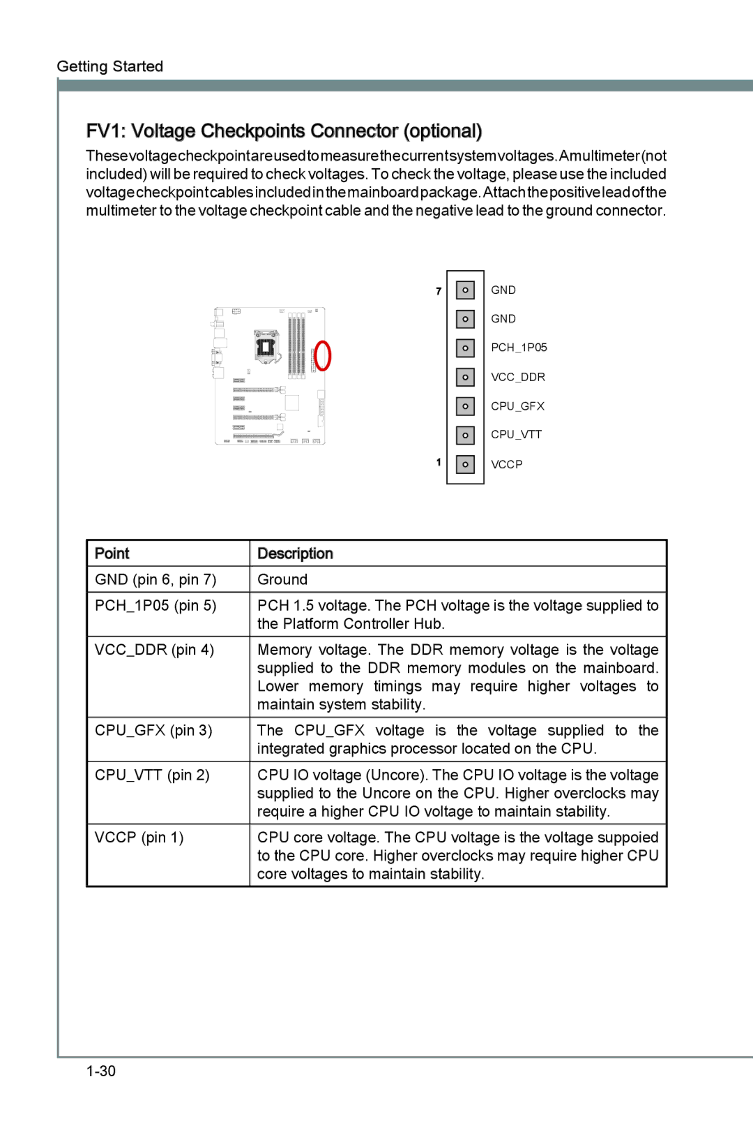
Thesevoltagecheckpointareusedtomeasurethecurrentsystemvoltages.Amultimeter(not included) will be required to check voltages. To check the voltage, please use the included voltagecheckpointcablesincludedinthemainboardpackage.Attachthepositiveleadofthe multimeter to the voltage checkpoint cable and the negative lead to the ground connector.
7
1
GND
GND
PCH_1P05
VCC_DDR
CPU_GFX
CPU_VTT
VCCP
Point | Description |
GND (pin 6, pin 7) | Ground |
PCH_1P05 (pin 5) | PCH 1.5 voltage. The PCH voltage is the voltage supplied to |
| the Platform Controller Hub. |
VCC_DDR (pin 4) | Memory voltage. The DDR memory voltage is the voltage |
| supplied to the DDR memory modules on the mainboard. |
| Lower memory timings may require higher voltages to |
| maintain system stability. |
CPU_GFX (pin 3) | The CPU_GFX voltage is the voltage supplied to the |
| integrated graphics processor located on the CPU. |
CPU_VTT (pin 2) | CPU IO voltage (Uncore). The CPU IO voltage is the voltage |
| supplied to the Uncore on the CPU. Higher overclocks may |
| require a higher CPU IO voltage to maintain stability. |
VCCP (pin 1) | CPU core voltage. The CPU voltage is the voltage suppoied |
| to the CPU core. Higher overclocks may require higher CPU |
| core voltages to maintain stability. |