Recoil Start Model shown
7HP Pony REAR-TINE Tiller
See Back Cover for Customer Service information
Training
Repairs, adjustments or inspections
Preparation
Operation
Maintenance and Storage
Keep children and pets away
Use slower engine speeds
Operating Symbols
Decals
To Avoid Serious Injury
Introduction
Hardware BAG Parts List
Inspect Unit
Attach Handlebars
Attach Forward Clutch Control Cable
Attach Reverse Clutch Control Cable
Check Transmission Gear OIL Level
ADD Motor OIL to Engine
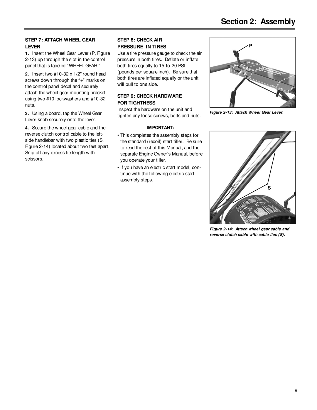
Attach Wheel Gear Lever
Check AIR Pressure in Tires
Check Hardware for Tightness
Battery Activation and Charging
Electric Start Assembly Steps
Install Battery
Attach Battery Cables and Vent Tube
Keyswitch
Connect Wiring Harness
Forward Clutch Control
Engine Controls
Wheel Gear Lever
To Operate the Forward Clutch Control
To Adjust the Handlebar Height
Handlebar Height Adjustment
Reverse Clutch Control
Depth Regulator
Engine Controls
Electric Start Keyswitch Electric Start Model
Engine Throttle Control Lever
Stop Stops the engine on recoil start models only
Starting and Stopping
PRE-START Checklist
Engine
BREAK-IN Operation
Starting the Engine
Operating the Tiller
Stopping the Engine
Release all controls on the tiller
For forward motion of the wheels and tines
Turning the Tiller Around
For reverse motion of the wheels and tines
Stopping the Tiller and Engine
Tilling depths
Let the tiller do the work
Avoid tilling soggy, wet soil
Avoid making footprints
Clearing the tines
Tilling across slopes without using terraces
Tilling on slopes
Tilling up and down slopes
Loading and Unloading the Tiller
Power Composting
Procedure
Required Maintenance Schedule
Tiller Lubrication
Every
Check Hardware
Transmission Gear OIL Service
Check Tire Pressure
Check for OIL Leaks
Engine OIL Service
Engine Cleaning
AIR Cleaner Service
CARBURETOR/GOVERNOR Control Adjustments
Wheel Gear Cable Adjustment
OFF Season Storage
Bolo Tines
Checking and Adjusting Forward Clutch Belt Tension
Checking and Adjusting Tension on Clutch Belts
Cutting Edge Tine
More Belt Tension
Checking and Adjusting Reverse Clutch Belt Tension
Removing Forward Clutch Belt
Installing Forward Clutch Belt
Removing Reverse Clutch Belt
Installing Reverse Clutch Belt
Battery Care in Service
Battery Maintenance
Battery Storage
Battery Removal and Installation
Bumper
HILLER/FURROWER
ROW Marker
Problem Possible Cause Correction
Troubleshooting
Models 12211
Part Description
QTY
See page 36, Ref 47, for attach Ment screw
Parts List
ENGINE, Support BRACKETS, PULLEYS, BELTS, Belt Cover
1917326
Part Description QTY
Main Drive Shaft
Input Pinion Shaft & Gear Assembly
Wheel SHAFT, Eccentric Shaft and Tiller Shaft Assemblies
Thicker than standard tines
Bolo TINES, Wheels
Electric Start Assembly
1918831001 Battery Bracket
ROW Marker Attachment
Bumper Attachment
2322
Row Marker Attachment option
ROW Marker Attachment & Bumper Attachment
Bumper
Description QTY
HILLER/FURROWER Attachment
Page
Replacement Parts
Warranty Service
Engine Service and Repair
Owner Registration Card