Auger Control Test

IMPORTANT: Perform the following test before operating your snow thrower for the first time and at the start of each winter season.

Check the adjustment of the auger control as follows:

When the auger control is released and in the disengaged “up” position, the cable should have very little slack. It should NOT be tight.

In a well-ventilated area, start the snow thrower engine as instructed earlier in this section under the heading Starting the Engine. Make sure the throttle is set in the FAST position.

While standing in the operator’s position (behind the snow thrower), engage the auger.

Allow the auger to remain engaged for approximately ten (10) seconds before releasing the auger control. Repeat this several times.

With the throttle control in the FAST (rabbit) position and the auger control in the disengaged “up” position, walk to the front of the machine.

Confirm that the auger has completely stopped rotating and shows NO signs of motion.

IMPORTANT: If the auger shows ANY signs of rotating, immediately return to the operator’s position and shut off the engine. Wait for ALL moving parts to stop before re-adjusting the auger control.

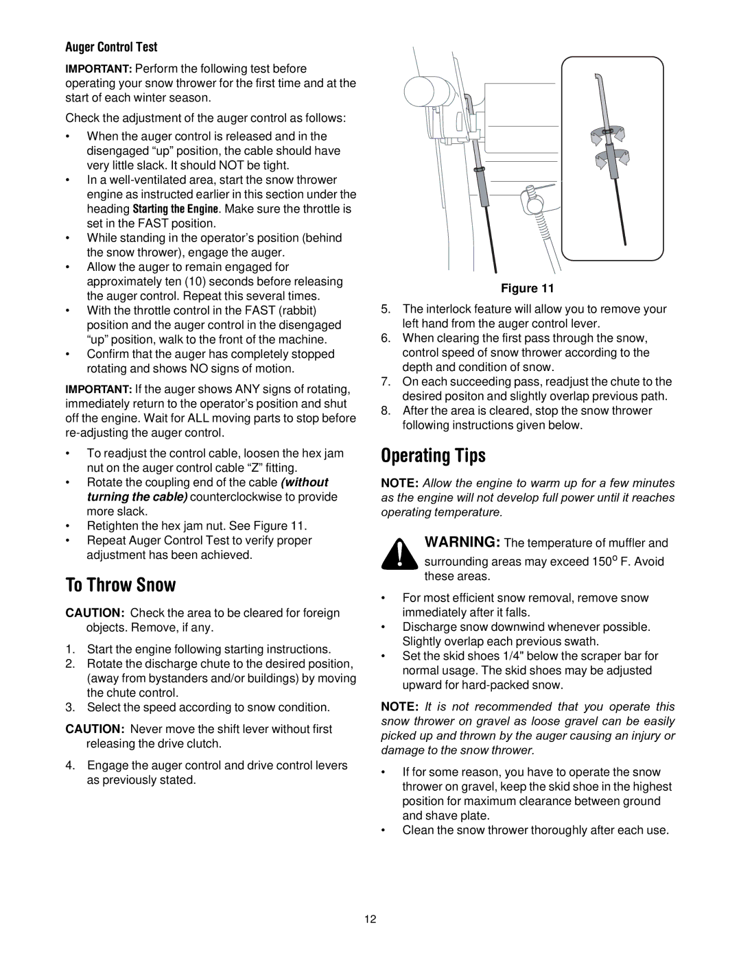
To readjust the control cable, loosen the hex jam nut on the auger control cable “Z” fitting.

Rotate the coupling end of the cable (without turning the cable) counterclockwise to provide more slack.

Retighten the hex jam nut. See Figure 11.

Repeat Auger Control Test to verify proper adjustment has been achieved.

To Throw Snow

CAUTION: Check the area to be cleared for foreign objects. Remove, if any.

1.Start the engine following starting instructions.

2.Rotate the discharge chute to the desired position, (away from bystanders and/or buildings) by moving the chute control.

3.Select the speed according to snow condition.

CAUTION: Never move the shift lever without first releasing the drive clutch.

4.Engage the auger control and drive control levers as previously stated.

Z Fitting

Hex Nut

Cable Should

Be Straight

Figure 11

5.The interlock feature will allow you to remove your left hand from the auger control lever.

6.When clearing the first pass through the snow, control speed of snow thrower according to the depth and condition of snow.

7.On each succeeding pass, readjust the chute to the desired positon and slightly overlap previous path.

8.After the area is cleared, stop the snow thrower following instructions given below.

Operating Tips

NOTE: Allow the engine to warm up for a few minutes as the engine will not develop full power until it reaches operating temperature.

WARNING: The temperature of muffler and

surrounding areas may exceed 150o F. Avoid these areas.

For most efficient snow removal, remove snow immediately after it falls.

Discharge snow downwind whenever possible. Slightly overlap each previous swath.

Set the skid shoes 1/4" below the scraper bar for normal usage. The skid shoes may be adjusted upward for hard-packed snow.

NOTE: It is not recommended that you operate this snow thrower on gravel as loose gravel can be easily picked up and thrown by the auger causing an injury or damage to the snow thrower.

If for some reason, you have to operate the snow thrower on gravel, keep the skid shoe in the highest position for maximum clearance between ground and shave plate.

Clean the snow thrower thoroughly after each use.

12

Page 12
Image 12
MTD 60-3754-4, 60-3753-6 manual To Throw Snow, Operating Tips

60-3753-6, 60-3754-4 specifications

The MTD 60-3753-6 and MTD 60-3754-4 are advanced mechanical components designed for a range of applications, primarily in landscaping, gardening, and outdoor power equipment. With an emphasis on durability and performance, these models are engineered to meet the demanding requirements of modern-day users.

One of the main features of the MTD 60-3753-6 is its robust construction. Built from high-quality materials, this component is designed to withstand the rigors of outdoor use, ensuring longevity and reliability. The 60-3754-4 complements this with its precision engineering, which reduces wear and tear, allowing for extended operational life. This focus on durability makes both components ideal for users who require consistent performance in challenging conditions.

In terms of technology, the MTD 60-3753-6 and 60-3754-4 incorporate innovative design elements that enhance their functionality. The use of advanced manufacturing techniques ensures that each component meets strict quality standards. Furthermore, these models are designed to provide easy installation and compatibility with a range of MTD equipment, making them user-friendly for technicians and DIY enthusiasts alike.

Another significant characteristic of these models is their versatility. The MTD 60-3753-6 is suitable for various applications, including tilling, mowing, and cultivating, while the 60-3754-4 can be used for tasks that require a flexible and durable component. This adaptability allows users to enjoy the benefits of these components across multiple equipment types, simplifying maintenance and part replacement.

Additionally, both models are designed with user comfort in mind. Ergonomic considerations have been incorporated, making these components easy to handle and operate. This focus on user experience is essential, especially for those using these components over extended periods.

In summary, the MTD 60-3753-6 and 60-3754-4 are exemplary models that showcase MTD's dedication to quality, innovation, and user satisfaction. Their robust construction, advanced technology, versatility, and ergonomic design make them indispensable for anyone seeking reliable mechanical components for their outdoor power equipment. Whether for professional landscaping or home gardening, these models provide the performance and durability that users can depend on.