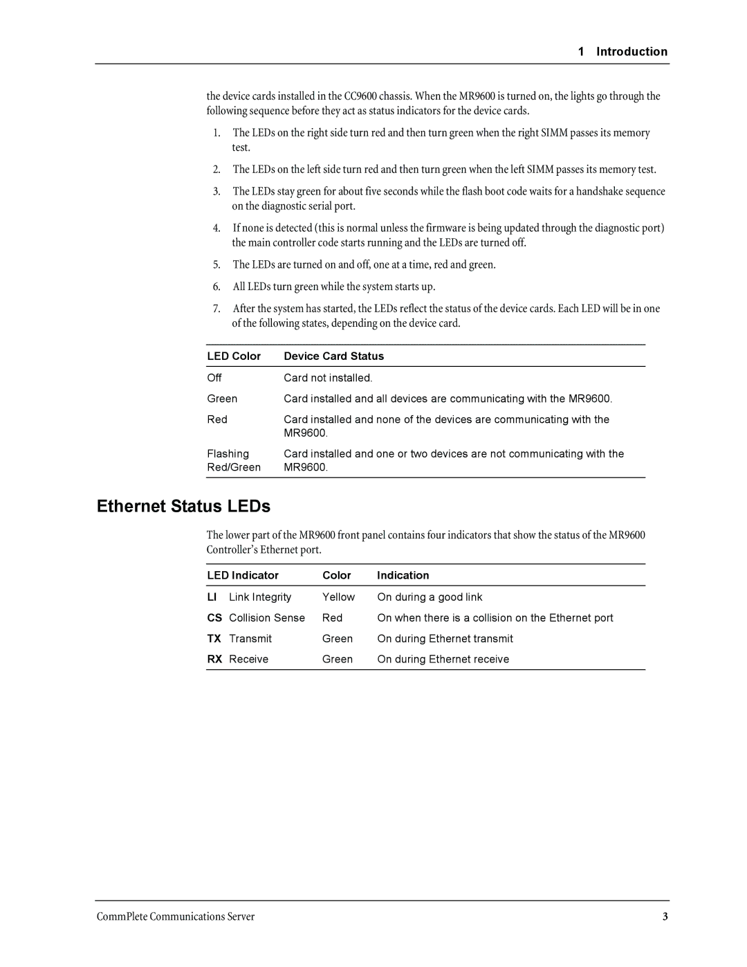
MR9600 specifications
Multi-Tech Systems MR9600 is a versatile and powerful device tailored for today's diverse communication needs, featuring advanced technology that ensures reliable connectivity and performance. This multi-purpose communication platform is primarily designed for applications in the Internet of Things (IoT), machine-to-machine (M2M) communications, and various telecommunication systems, providing seamless data transmission across multiple networks.One of the standout features of the MR9600 is its integrated 4G LTE capability, offering high-speed cellular connectivity. This ensures that users can maintain uninterrupted communication regardless of their geographic location. The device supports a wide range of LTE bands, making it compatible with numerous cellular networks worldwide. Additionally, the MR9600 is equipped with fall-back support for 3G networks, providing a safety net for areas with limited 4G coverage.
The MR9600 is designed with a variety of interfaces, including Ethernet, serial, and USB ports, allowing for easy integration with legacy systems and modern devices. This flexibility ensures that the MR9600 can be deployed in numerous environments, from industrial automation to smart city applications, making it a go-to solution for system integrators and developers looking to enhance connectivity.
Security is another essential aspect of the MR9600, featuring built-in security protocols that protect data transmission and device integrity. With secure access controls, including VPN and firewall capabilities, users can rest assured that their information remains safe from potential threats.
Furthermore, the MR9600 supports over-the-air (OTA) firmware updates, allowing for streamlined management and maintenance of devices in the field. This feature reduces downtime and enhances operational efficiency, enabling businesses to scale their IoT deployments effortlessly.
In summary, the Multi-Tech Systems MR9600 combines advanced 4G LTE technology, multiple connectivity options, and robust security features to deliver a reliable and efficient communication solution. Its versatility makes it suitable for a wide array of applications, solidifying its place as a leading choice for enterprises looking to optimize their communication capabilities in an increasingly connected world.

