components
16
10 2
1
4
14 | 12 |
15 ![]()
3
6
5
9
7
13 12
11
8
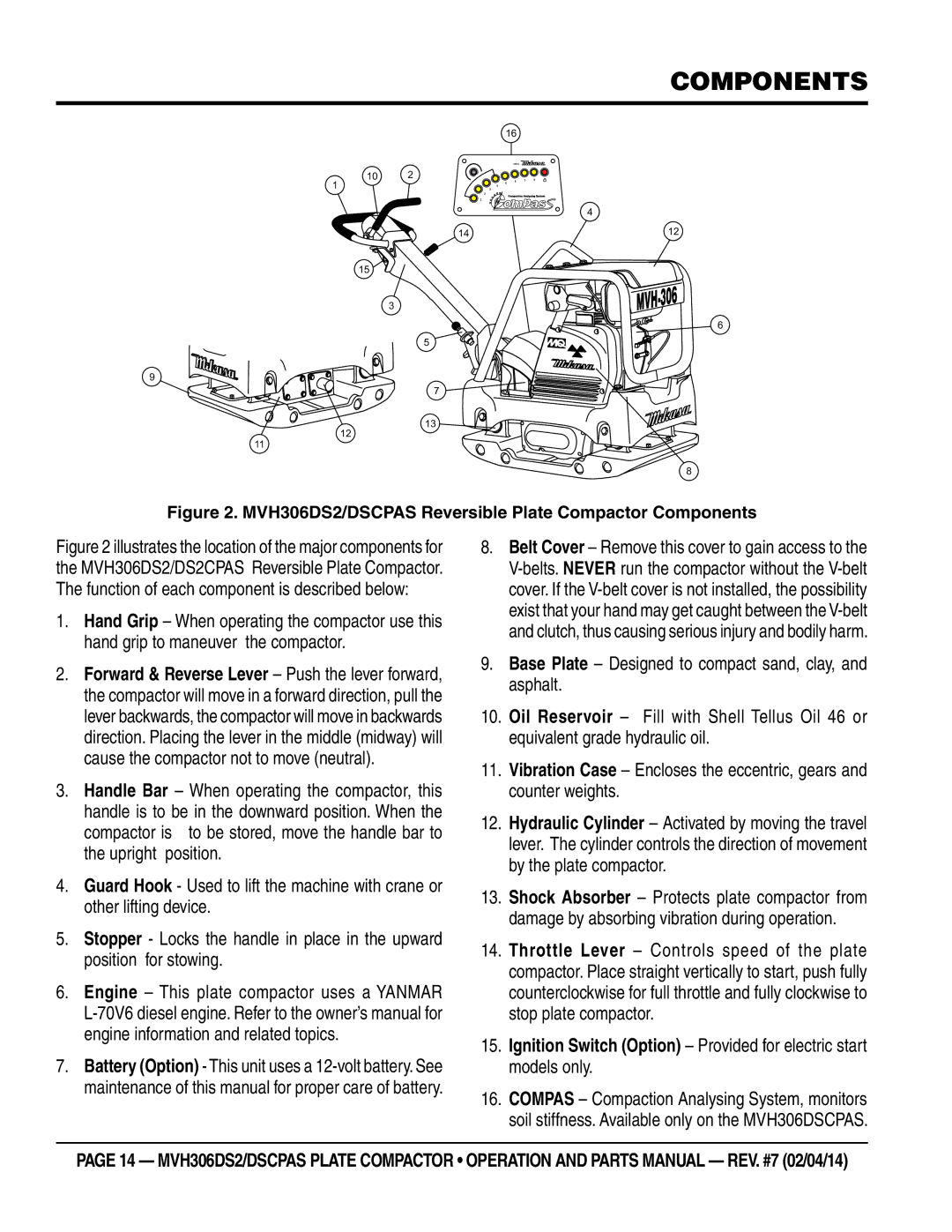
Figure 2. MVH306DS2/DSCPAS Reversible Plate Compactor Components
Figure 2 illustrates the location of the major components for the MVH306DS2/DS2CPAS Reversible Plate Compactor. The function of each component is described below:
1.Hand Grip – When operating the compactor use this hand grip to maneuver the compactor.
2.Forward & Reverse Lever – Push the lever forward, the compactor will move in a forward direction, pull the lever backwards, the compactor will move in backwards direction. Placing the lever in the middle (midway) will cause the compactor not to move (neutral).
3.Handle Bar – When operating the compactor, this
handle is to be in the downward position. When the compactor is to be stored, move the handle bar to the upright position.
4.Guard Hook - Used to lift the machine with crane or other lifting device.
5.Stopper - Locks the handle in place in the upward position for stowing.
6.Engine – This plate compactor uses a YANMAR
7.Battery (Option) - This unit uses a
8.Belt Cover – Remove this cover to gain access to the
9.Base Plate – Designed to compact sand, clay, and asphalt.
10.Oil Reservoir – Fill with Shell Tellus Oil 46 or equivalent grade hydraulic oil.
11.Vibration Case – Encloses the eccentric, gears and counter weights.
12.Hydraulic Cylinder – Activated by moving the travel lever. The cylinder controls the direction of movement by the plate compactor.
13.Shock Absorber – Protects plate compactor from damage by absorbing vibration during operation.
14.Throttle Lever – Controls speed of the plate compactor. Place straight vertically to start, push fully counterclockwise for full throttle and fully clockwise to stop plate compactor.
15.Ignition Switch (Option) – Provided for electric start models only.
16.COMPAS – Compaction Analysing System, monitors soil stiffness. Available only on the MVH306DSCPAS.
page 14 — mvh306ds2/dsCPAs pLATE COMPACTOR • operation and parts manual — rev. #7 (02/04/14)
