DCA-180SSV— GENERATOR START-UP PROCEDURE (MANUAL)
Before Starting
CAUTION - LETHAL EXHAUST HAZARD
The engine's exhaust contains harmful emissions.
ALWAYS have adequate ventilation when operating.
Direct exhaust away from nearby personnel.
WARNING - STARTINGTHE GENERATOR
NEVER! manually start the engine with the main, GFCI or auxiliary circuit breakers in the ON (closed) position.
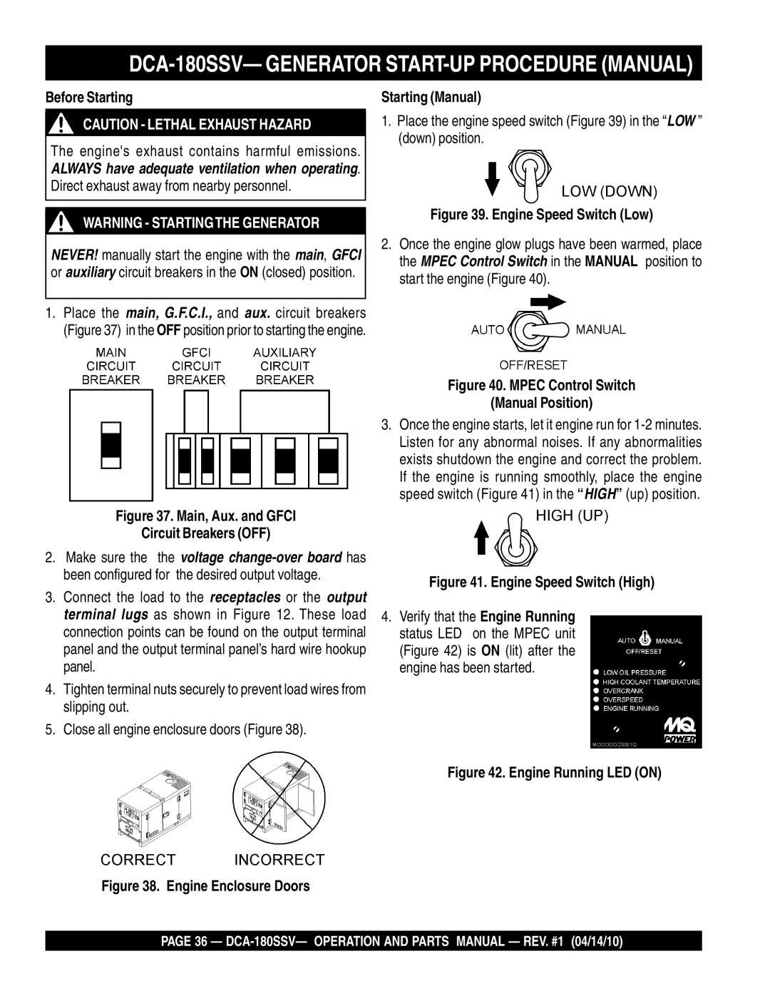
1.Place the main, G.F.C.I., and aux. circuit breakers (Figure 37) in the OFF position prior to starting the engine.
Figure 37. Main, Aux. and GFCI
Circuit Breakers (OFF)
2.Make sure the the voltage
3.Connect the load to the receptacles or the output terminal lugs as shown in Figure 12. These load connection points can be found on the output terminal panel and the output terminal panel’s hard wire hookup panel.
4.Tighten terminal nuts securely to prevent load wires from slipping out.
5.Close all engine enclosure doors (Figure 38).
Starting (Manual)
1.Place the engine speed switch (Figure 39) in the “LOW ” (down) position.
Figure 39. Engine Speed Switch (Low)
2.Once the engine glow plugs have been warmed, place the MPEC Control Switch in the MANUAL position to start the engine (Figure 40).
Figure 40. MPEC Control Switch
(Manual Position)
3.Once the engine starts, let it engine run for
Figure 41. Engine Speed Switch (High)
4.Verify that the Engine Running status LED on the MPEC unit (Figure 42) is ON (lit) after the engine has been started.
Figure 42. Engine Running LED (ON)
Figure 38. Engine Enclosure Doors
PAGE 36 —