DCA-70SSJU SERIES — GENERATOR START-UP PROCEDURE (MANUAL)
WARNING:
The engine's exhaust contains harmful emissions. ALWAYS have adequate ventilation when operating. Direct exhaust away from nearby personnel.
Before Starting
Engine Operating Panel S/N 73002140 and below
CAUTION:
NEVER! manually start the engine with the main, GFCI or auailliary circuit breakers in the ON (closed) position.
NOTE
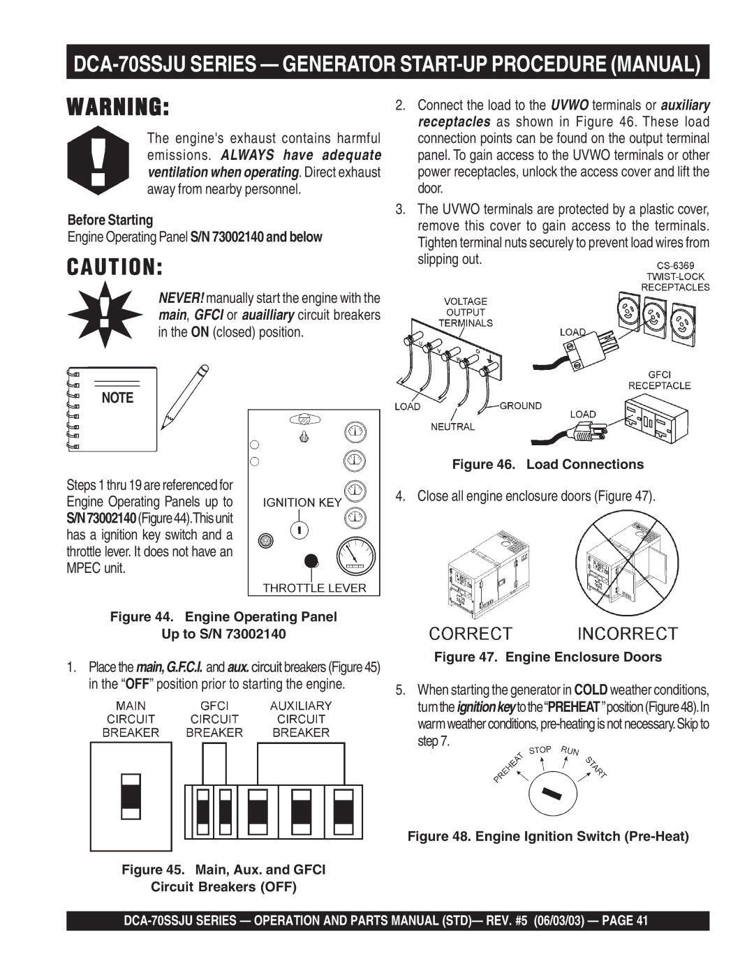
2.Connect the load to the UVWO terminals or auxiliary receptacles as shown in Figure 46. These load connection points can be found on the output terminal panel. To gain access to the UVWO terminals or other power receptacles, unlock the access cover and lift the door.
3.The UVWO terminals are protected by a plastic cover, remove this cover to gain access to the terminals. Tighten terminal nuts securely to prevent load wires from slipping out.
Steps 1 thru 19 are referenced for Engine Operating Panels up to S/N73002140(Figure44).Thisunit has a ignition key switch and a throttle lever. It does not have an MPEC unit.
Figure 46. Load Connections
4. Close all engine enclosure doors (Figure 47).
Figure 44. Engine Operating Panel
Up to S/N 73002140
1.Place the main,G.F.C.I. and aux. circuit breakers (Figure 45) in the “OFF” position prior to starting the engine.
Figure 45. Main, Aux. and GFCI
Circuit Breakers (OFF)
Figure 47. Engine Enclosure Doors
5.When starting the generator in COLD weather conditions, turntheignitionkeytothe“PREHEAT”position(Figure48).In warm weather conditions,