OUTPUT TERMINAL PANEL CONNECTIONS
3. Turn the voltage regulator knob (Figure 20) clockwise to increase voltage output, turn counterclockwise to decrease voltage output. Use voltage regulator adjustment knob whenever fine tuning of the output voltage is required
Figure 20. Voltage Regulator Knob
1Ø-240V UVWO Terminal Output Voltages
1. Make sure the voltage
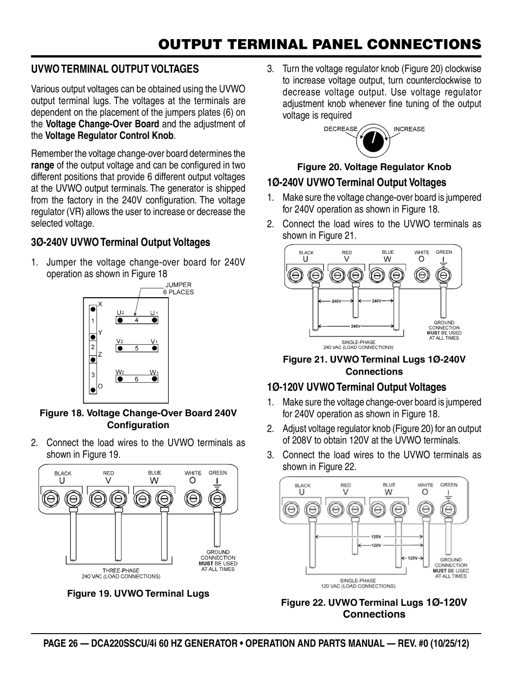
2. Connect the load wires to the UVWO terminals as shown in Figure 21.
1.Jumper the voltage
Figure 21. UVWO Terminal Lugs 1Ø-240V
Connections
1Ø-120V UVWO Terminal Output Voltages
1. Make sure the voltage
2. Adjust voltage regulator knob (Figure 20) for an output of 208V to obtain 120V at the UVWO terminals.
3. Connect the load wires to the UVWO terminals as shown in Figure 22.
Figure 22. UVWO Terminal Lugs 1Ø-120V
Connections
page 26 — dca220sscu/4i 60 hz generator • operation and Parts manual — rev. #0 (10/25/12)