ENGINE/Generator Control Panel
|
|
| 1 |
|
|
|
|
50 | A |
| 180 | B |
| 18 | C |
25 | 75 |
| 140 | 220 |
| 12 | 24 |
PSI |
|
| °F |
|
| VOLTS |
|
0 | 100 | 100 | 260 |
| 6 | 30 | |
OIL PRESS |
| WATER TEMP |
| BATTERY | |||
|
| D | ½ |
| E | 150 |
|
|
|
|
|
|
| 120 | 180 |
|
|
|
|
|
| 60 |
|
|
|
| °F |
|
| RPMX10 | |
|
| E |
| F |
| 0 | 210 |
|
|
| FUEL |
|
| SPEED |
|
|
|
|
| 2 | |
25 | 50 |
| 180 |
| 18 |
75 | 140 | 220 | 12 | 24 | |
0 | PSI |
| °F |
| VOLTS |
100 | 100 | 260 | 6 | 30 | |
OIL PRESS | WATER TEMP |
| BATTERY | ||
½150
|
| 120 | 180 |
|
| 60 |
|
| °F | RPMX10 | |
E | F | 0 | 210 |
FUELSPEED
ECU Series 800 Controller
Engine Started ![]()
Shutdown ![]()
![]()
Alarm | Screen | Option | Program |
Acknowledge Change | Exit | ||
3
4
7
INCREASEDECREASE
8
V
U W
OFF
59
OFF
6
14
131110
12
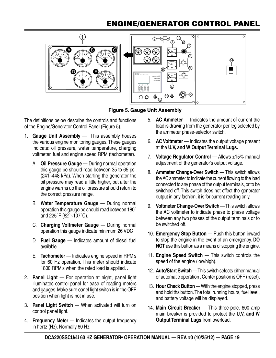
Figure 5. Gauge Unit Assembly
The definitions below describe the controls and functions of the Engine/Generator Control Panel (Figure 5).
1.Gauge Unit Assembly — This assembly houses the various engine monitoring gauges. These gauges indicate: oil pressure, water temperature, charging voltmeter, fuel and engine speed RPM (tachometer).
A.Oil Pressure Gauge — During normal operation this gauge be should read between 35 to 65 psi. (241~448 kPa). When starting the generator the oil pressure may read a little higher, but after the engine warms up the oil pressure should return to the correct pressure range.
B.Water Temperature Gauge — During normal operation this gauge be should read between 180° and 225°F (82°~107°C).
C.Charging Voltmeter Gauge — During normal operation this gauge indicate minimum 26 VDC
D.Fuel Gauge — Indicates amount of diesel fuel available.
E.Tachometer — Indicates engine speed in RPM’s for 60 Hz operation. This meter should indicate 1800 RPM’s when the rated load is applied. .
2.Panel Light — For operation at night, panel light illuminates control panel for ease of reading meters and gauges. Make sure oanel light switch is in the OFF position when light is not in use.
3.Panel Light Switch — When activated will turn on control panel light.
4.Frequency Meter — Indicates the output frequency in hertz (Hz). Normally 60 Hz
5.AC Ammeter — Indicates the amount of current the load is drawing from the generator per leg selected by the ammeter
6.AC Voltmeter — Indicates the output voltage present at the U,V, and W Output Terminal Lugs.
7.Voltage Regulator Control — Allows ±15% manual adjustment of the generator’s output voltage.
8.Ammeter
9.Voltmeter
10.Emergency Stop Button — Push this button inward to stop the engine in the event of an emergency. DO NOT use this button as a means of stopping the engine.
11.Engine Speed Switch — This switch controls the speed of the engine (low/high).
12.Auto/Start Switch — This switch selects either manual or automatic operation . Center position is OFF (reset).
13.Hour Check Button — With the engine stopped, press and hold ths button. The total running hours, fuel level, and battery voltage will be displayed.
14.Main Circuit Breaker — This
DCA220ssCU/4i 60 hz generator• operation manual — rev. #0 (10/25/12) — page 19