GLOBUG LIGHTING SYSTEM — PRE-SETUP
CAUTION - Read Manual
Please read this entire manual carefully before attempting to operate the GloBug. Failure to read this manual could cause damage to the GloBug and serious injury to the operator.
GloBug Setup
1.Using the
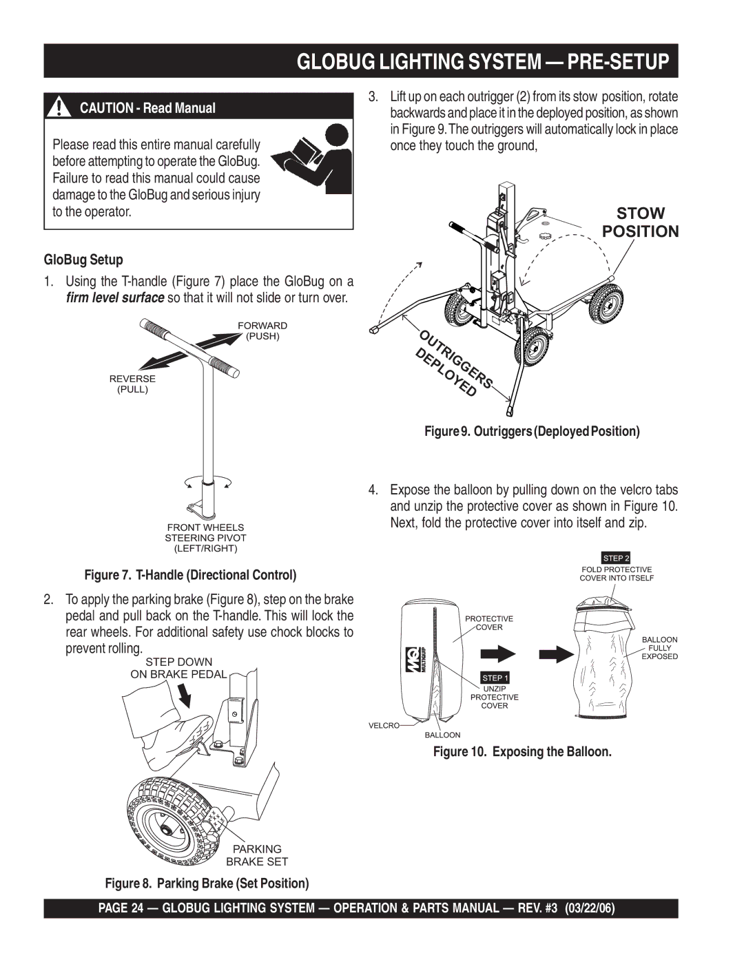
3.Lift up on each outrigger (2) from its stow position, rotate backwards and place it in the deployed position, as shown in Figure 9.The outriggers will automatically lock in place once they touch the ground,
STOW
POSITION
DEPLOYEDOUTRIGGERS
Figure 9. Outriggers (Deployed Position)
4.Expose the balloon by pulling down on the velcro tabs and unzip the protective cover as shown in Figure 10.
Next, fold the protective cover into itself and zip.
Figure 7. T-Handle (Directional Control)
2. To apply the parking brake (Figure 8), step on the brake pedal and pull back on the
STEP DOWN
ON BRAKE PEDAL
Figure 10. Exposing the Balloon.
PARKING
BRAKE SET
Figure 8. Parking Brake (Set Position)
PAGE 24 — GLOBUG LIGHTING SYSTEM — OPERATION & PARTS MANUAL — REV. #3 (03/22/06)