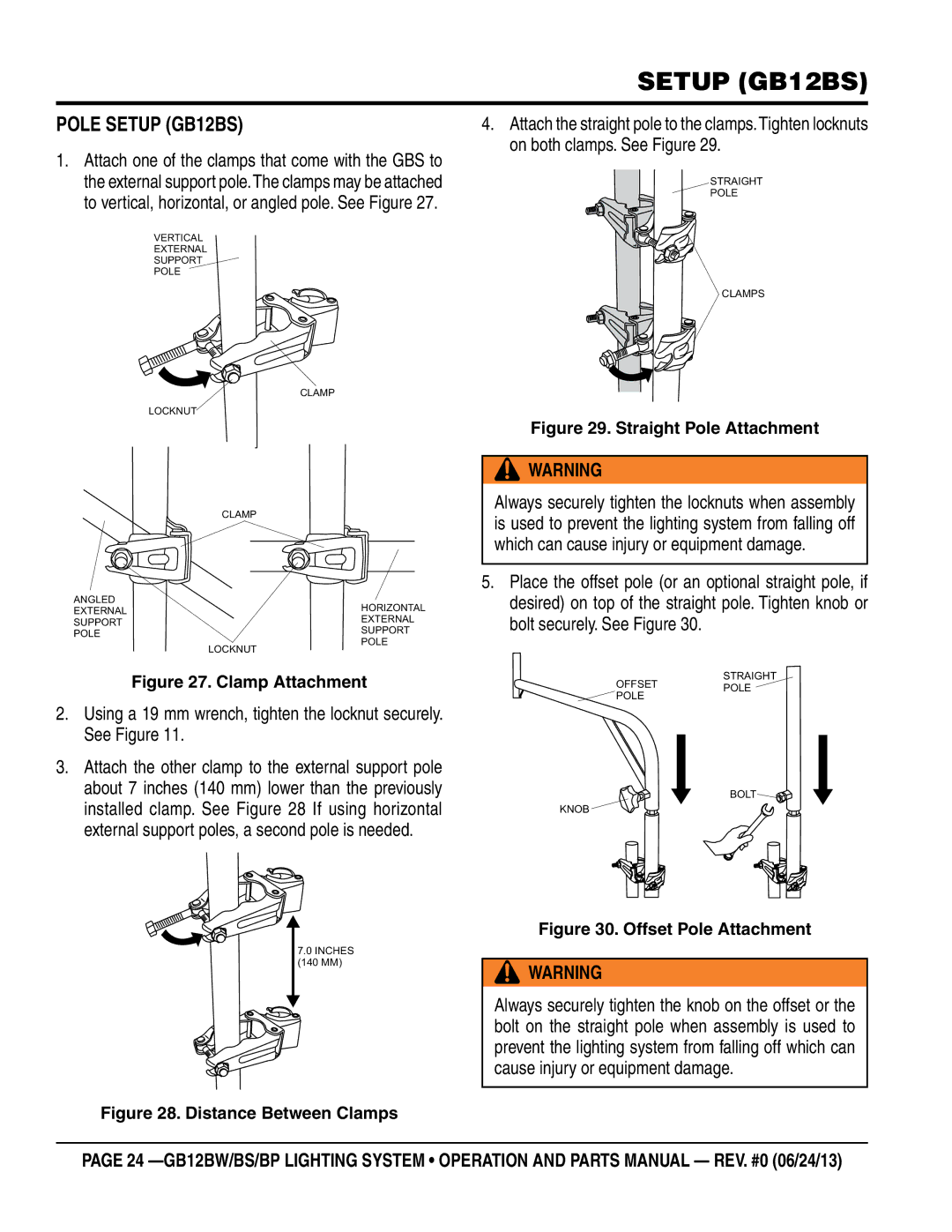
GB12BS, GB12BP, GB12BW specifications
The Multiquip GB12 series of concrete trowels, including the GB12BW, GB12BP, and GB12BS models, represents a significant advancement in concrete finishing technology. These trowels are engineered to deliver optimal performance and efficiency on job sites, making them indispensable for contractors and professionals in the field.One of the standout features of the GB12 series is its robust and durable design. Constructed with high-quality materials, these trowels are built to withstand the rigors of heavy use while maintaining precision and reliability. The GB12BW model is particularly notable for its weight distribution, which allows for a smooth finish on larger surfaces. Its blade size is engineered to cover expansive areas rapidly, making it an excellent choice for large projects.
The GB12BP variant caters to those seeking a powered trowel that can deliver enhanced performance with less manual effort. It is equipped with a powerful engine that offers substantial torque, allowing for efficient concrete finishing, even in challenging conditions. This model emphasizes user comfort and control, featuring an ergonomic handle system that reduces operator fatigue during extended use.
For those who prioritize safety, the GB12BS model includes advanced safety features designed to mitigate risks on job sites. Safety guards and emergency stop controls are integrated into the design, ensuring that operators can quickly halt operations if necessary. These features are crucial for maintaining a secure working environment, especially when operating heavy machinery like trowels.
The trowels in the GB12 series offer versatility in finishing options. Equipped with interchangeable blade types, users can select different blade configurations to achieve varied surface textures, from a smooth finish to a rougher surface. Additionally, the adjustable pitch control allows operators to fine-tune the angle of the blades, accommodating different finishing styles and concrete types.
Moreover, these trowels are designed with ease of maintenance in mind. Quick-release features enable operators to swap out blades and perform routine maintenance without extensive downtime. This focus on user-friendly design ensures that the Multiquip GB12 series remains a preferred choice among professionals who demand efficiency and reliability in their equipment.
In conclusion, the Multiquip GB12BW, GB12BP, and GB12BS trowels offer a sophisticated blend of performance, safety, and versatility. Their durable construction, innovative technologies, and thoughtful design make them ideal for concrete finishing tasks of any scale, cementing their status as top-tier equipment in the construction industry.

