operation
operation
1.Connect the vibrator to the proper power source.
2.If an extension cord is necessary, refer to Table 5 for the correct type of extension cord to use.
Table 5. Extension Cord Types
Current | Load in Watts | Maximum Allowable Cable Length | |||||
|
|
|
|
|
| ||
in | At 100 | At 200 | #10 Wire | #12 Wire | #14 Wire | #16 Wire | |
Amperes | |||||||
Volts | Volts | ||||||
|
|
|
|
| |||
|
|
|
|
|
|
| |
2.5 | 300 | 600 | 1000 ft. | 600 ft. | 375 ft. | 250 ft. | |
|
|
|
|
|
|
| |
5 | 600 | 1200 | 500 ft. | 300 ft. | 200 ft. | 125 ft. | |
|
|
|
|
|
|
| |
7.5 | 900 | 1800 | 350 ft. | 200 ft. | 125 ft. | 100 ft. | |
|
|
|
|
|
|
| |
10 | 1200 | 2400 | 250 ft. | 150 ft. | 100 ft. |
| |
|
|
|
|
|
|
| |
15 | 1800 | 3600 | 150 ft. | 100 ft. | 65 ft. |
| |
|
|
|
|
|
|
| |
20 | 2400 | 4800 | 125 ft. | 75 ft. | 50 ft. |
| |
|
|
|
|
|
|
| |
3.Hold vibrator head above concrete pour when starting drive motor. This will prevent the vibrator head from bouncing on hard surfaces which could damage the bearings.
4.Push the ON/OFF switch to the ON position then immerse into the surface. Do not run the motor outside of the surface for long periods.
![]()
![]() NOTICE
NOTICE
Pressing the Power Lock Button will lock the On/OFF switch to the ON position.
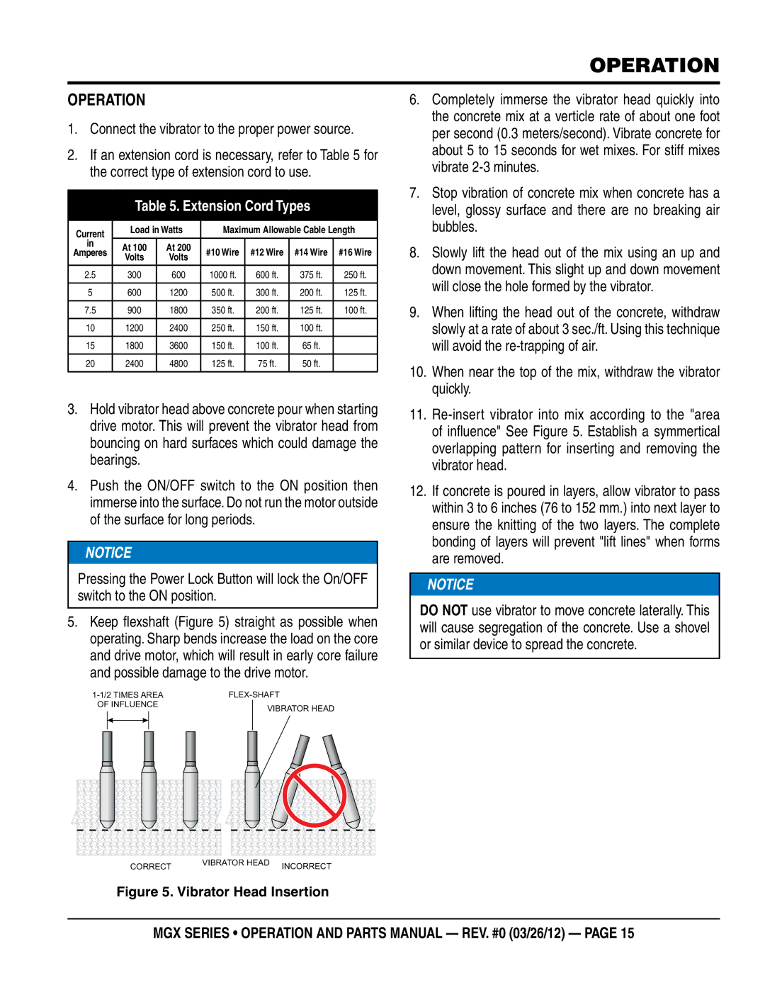
5.Keep flexshaft (Figure 5) straight as possible when operating. Sharp bends increase the load on the core and drive motor, which will result in early core failure and possible damage to the drive motor.
| ||||||||||||
OF INFLUENCE |
|
|
|
| VIBRATOR HEAD | |||||||
|
|
|
|
|
|
|
|
|
|
|
| |
|
|
|
|
|
|
|
|
|
|
|
|
|
|
|
|
|
|
|
|
|
|
|
|
|
|
|
|
|
|
|
|
|
|
|
|
|
|
|
|
|
|
|
|
|
|
|
|
|
|
|
|
|
|
|
|
|
|
|
|
|
|
|
|
|
6.Completely immerse the vibrator head quickly into the concrete mix at a verticle rate of about one foot per second (0.3 meters/second). Vibrate concrete for about 5 to 15 seconds for wet mixes. For stiff mixes vibrate
7.Stop vibration of concrete mix when concrete has a level, glossy surface and there are no breaking air bubbles.
8.Slowly lift the head out of the mix using an up and down movement. This slight up and down movement will close the hole formed by the vibrator.
9.When lifting the head out of the concrete, withdraw slowly at a rate of about 3 sec./ft. Using this technique will avoid the
10.When near the top of the mix, withdraw the vibrator quickly.
11.
12.If concrete is poured in layers, allow vibrator to pass within 3 to 6 inches (76 to 152 mm.) into next layer to ensure the knitting of the two layers. The complete bonding of layers will prevent "lift lines" when forms are removed.
![]() NOTICE
NOTICE
DO NOT use vibrator to move concrete laterally. This will cause segregation of the concrete. Use a shovel or similar device to spread the concrete.
CORRECT | VIBRATOR HEAD | INCORRECT |
|
Figure 5. Vibrator Head Insertion
mgx Series • operation and parts manual — rev. #0 (03/26/12) — page 15
