COMPONENTS
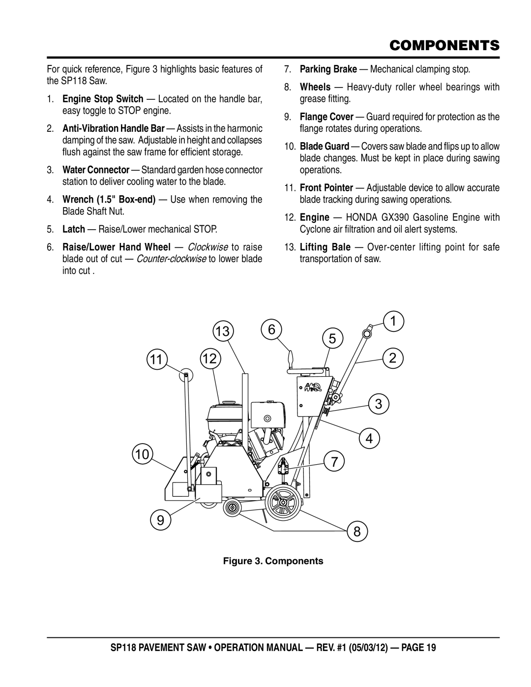
For quick reference, Figure 3 highlights basic features of the SP118 Saw.
1.Engine Stop Switch — Located on the handle bar, easy toggle to STOP engine.
2.
3.Water Connector — Standard garden hose connector station to deliver cooling water to the blade.
4.Wrench (1.5"
5.Latch — Raise/Lower mechanical STOP.
6.Raise/Lower Hand Wheel — Clockwise to raise blade out of cut —
7.Parking Brake — Mechanical clamping stop.
8.Wheels —
9.Flange Cover — Guard required for protection as the flange rotates during operations.
10.Blade Guard — Covers saw blade and flips up to allow blade changes. Must be kept in place during sawing operations.
11.Front Pointer — Adjustable device to allow accurate blade tracking during sawing operations.
12.Engine — HONDA GX390 Gasoline Engine with Cyclone air filtration and oil alert systems.
13.Lifting Bale —
13 6 5
1
11 | 12 | 2 |
10
3
4
7
9
8
Figure 3. Components
SP118 Pavement Saw • operation manual — rev. #1 (05/03/12) — page 19