electric motor components/set-up
Electric Motor Components
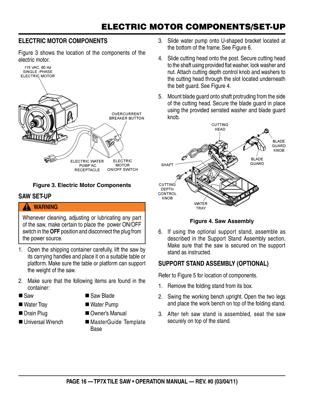
Figure 3 shows the location of the components of the electric motor.
115 VAC, 60 Hz
SINGLE
ELECTRIC MOTOR
OVERCURRENT
BREAKER BUTTON
ELECTRIC WATER | ELECTRIC |
PUMP AC | MOTOR |
RECEPTACLE | ON/OFF SWITCH |
Figure 3. Electric Motor Components
Saw Set-Up
![]() WARNING
WARNING
Whenever cleaning, adjusting or lubricating any part of the saw, make certain to place the power ON/OFF switch in the OFF position and disconnect the plug from the power source.
1.Open the shipping container carefully, lift the saw by its carrying handles and place it on a suitable table or platform. Make sure the table or platform can support the weight of the saw.
2.Make sure that the following items are found in the container:
Saw | Saw Blade |
Water Tray | Water Pump |
Drain Plug | Owner’s Manual |
Universal Wrench | MasterGuide Template |
| Base |
3.Slide water pump onto
4.Slide cutting head onto the post. Secure cutting head to the shaft using provided flat washer, lock washer and nut. Attach cutting depth control knob and washers to the cutting head through the slot located underneath the belt guard. See Figure 4.
5.Mount blade guard onto shaft protruding from the side of the cutting head. Secure the blade guard in place using the provided serrated washer and blade guard knob.
CUTTING
HEAD
BLADE
GUARD
KNOB
| BLADE |
SHAFT | GUARD |
|
CUTTING
DEPTH
CONTROL
KNOB
WATER
TRAY
Figure 4. Saw Assembly
6.If using the optional support stand, assemble as described in the Support Stand Assembly section. Make sure that the saw is secured on the support stand as instructed.
support Stand Assembly (Optional)
Refer to Figure 5 for location of components.
1.Remove the folding stand from its box.
2.Swing the working bench upright. Open the two legs and place the work bench on top of the folding stand.
3.After teh saw stand is assembled, seat the saw securely on top of the stand.
page 16 — TP7X TILE SAW • operation manual — rev. #0 (03/04/11)