Manuals
/
Multitech
/
Computer Equipment
/
Network Card
Multitech
MTPSR1-120
manual
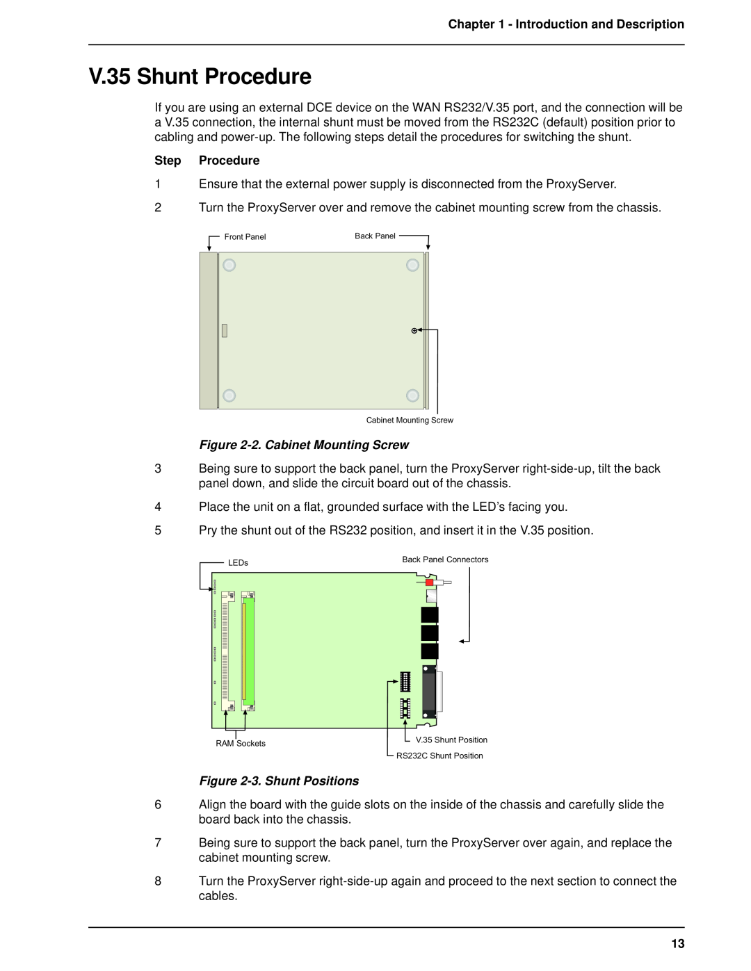
V.35 Shunt Procedure, Step Procedure, 2. Cabinet Mounting Screw
Models:
MTPSR1-120
1
13
60
60
Download
60 pages
19.51 Kb
10
11
12
13
14
15
16
17
Specs
Install
Warranty
IP Port Configuration
RS232/V.35 Connector
V.35 Shunt Procedure
Default WAN Link Configuration
Safety
Power
Internet Services Network
Page 13
Image 13
Page 12
Page 14
Page 13
Image 13
Page 12
Page 14
Contents
User Guide
Dual Ethernet ProxyServer Model MTPSR1-120
Record of Revisions RevisionDescription
User Guide
Patents
TRADEMARK
Chapter 3 - Software Loading and Configuration
Chapter 2 - Installation
Chapter 1 - Introduction and Description
Chapter 4 - Firewall Software
Chapter 6 - Warranty, Service and Tech Support
Chapter 5 - Remote Configuration and Management
Appendixes
Index
Chapter 1 - Introduction and Description
Chapter 3 - Software Loading and Configuration
Chapter 2 - Installation
Introduction
Preview of this Guide
Chapter 6 - Warranty, Service and Tech Support
Chapter 5 - Remote Configuration and Management
Chapter 4 - ProxyServer Software
Appendixes
Front Panel Description
Power
ETHERNET 1 and
WAN Link
Ethernet 1 and 2 10Base-T Connectors
RS232/V.35 Connector
Command Connector
Power Connector
Command Port
Specifications
Ethernet Ports
WAN Link
Chapter 2 - Installation
Unpacking Your ProxyServer
Safety Warnings
Figure 2-1. Unpacking
Step Procedure
V.35 Shunt Procedure
Figure 2-2. Cabinet Mounting Screw
Figure 2-3. Shunt Positions
Cabling Your ProxyServer
Cabling Procedure Step Procedure
Figure 2-4. Cable Connections
Chapter 2 - Installation Table 2-1. cont’d Step Procedure
Dual Ethernet ProxyServer User Guide
Chapter 3 - Software Loading and Configuration
Loading Your Software
7. The “Do you want to download default setup?” dialog is displayed
Chapter 3 - Software Loading and Configuration
DHCP Relay Agent does not apply
IP Port Configuration
Default WAN Link Configuration
19. The Writing Setup dialog box is displayed as the setup configuration is written to the ProxyServer
Chapter 4 - Firewall Software
Figure 4-1. Cable/DSL Modem Configuration
Configuration 1 - Cable/DSL Modem
Typical Applications
Private LAN
Chapter 4 - Firewall Software
Figure 4-2. Existing Dual-LAN with Router Configuration
Configuration 2 - Existing Dual-LAN with Router
Internet Services Network
Private LAN
Figure 4-3. New Dual-LAN with T1 DSU Configuration
Configuration 3 - New Dual-LAN with T1 DSU
The Internet LAN Port Parameters group is either configured with the DHCP Client option active, enabling the ISP to dynamically provide the registered Internet IP addresses, or with the DHCP Client option disabled if a static IP addressing scheme is provided by the ISP. If the DHCP Client field is deactivated the static IP Address of 204.26.12.10 is then entered and the WAN option is checked in the Internet Gateway Parameters group
Download Default Setup
Configuration Port Setup
Firewall Program Group
Uninstall Firewall Configuration
Download Firmware Update
WAN Device Configuration
Firewall Configuration
Changing IP Parameters
Net Mask - Enter the Subnetwork Mask for the WAN port in this field
Changing WAN Port Parameters
Adding Proxy Applications
Enabling the DHCP Server
Enabling PPP/SLIP
Chapter 5 - Remote Configuration and Management
Enabling PPP
Enabling SLIP
Statistics
Applications
Filtering
Chapter 5 - Remote Configuration and Management
Connect the modem to your local telephone line
Modem-Based Remote Configuration Procedure
Click OK when you are satisfied with your selections
Windows Sockets Compliant TCP/IP Stack
LAN-Based Remote Configuration Procedure
8 Click Exit when the downloading is complete
Telnet
Remote Management
Firewall Management Menu
Firewall Configuration
The Firewall Management Menu provides two basic options Firewall Configuration and WAN Device Configuration. A further option enables you to close the Telnet session from this menu by pressing the Esc key
WEB Management
Chapter 6 - Warranty, Service and Tech Support
On-line Warranty Registration
Limited Warranty
Tech Support
Chapter 6 - Warranty, Service and Technical Support
Recording ProxyServer Information
ATTN SERVICE OR REPAIRS
Service
MULTI-TECH SYSTEMS, INC 2205 WOODALE DRIVE MOUNDS VIEW, MINNESOTA
To Log on to the Multi-Tech BBS
The Multi-Tech BBS
To Download a File
If you know the file name
About CompuServe
About the Multi-Tech Fax-Back Service
About the Internet
ftp//ftp.multitech.com
Appendixes
Dual Ethernet ProxyServer User Guide
Appendix A - TCP/IP Description
Internet Protocol IP
Index F
Configuration 3 - New Dual-LAN with T1 DSU
Configuration 2 - Existing Dual-LAN with Router26
Secured LAN Port Parameters
20, 33
Top
Page
Image
Contents