Pressure Vessel Installation: LS200, LS200N and L1100
Direct Installation into the Wall of the Pressure Vessel
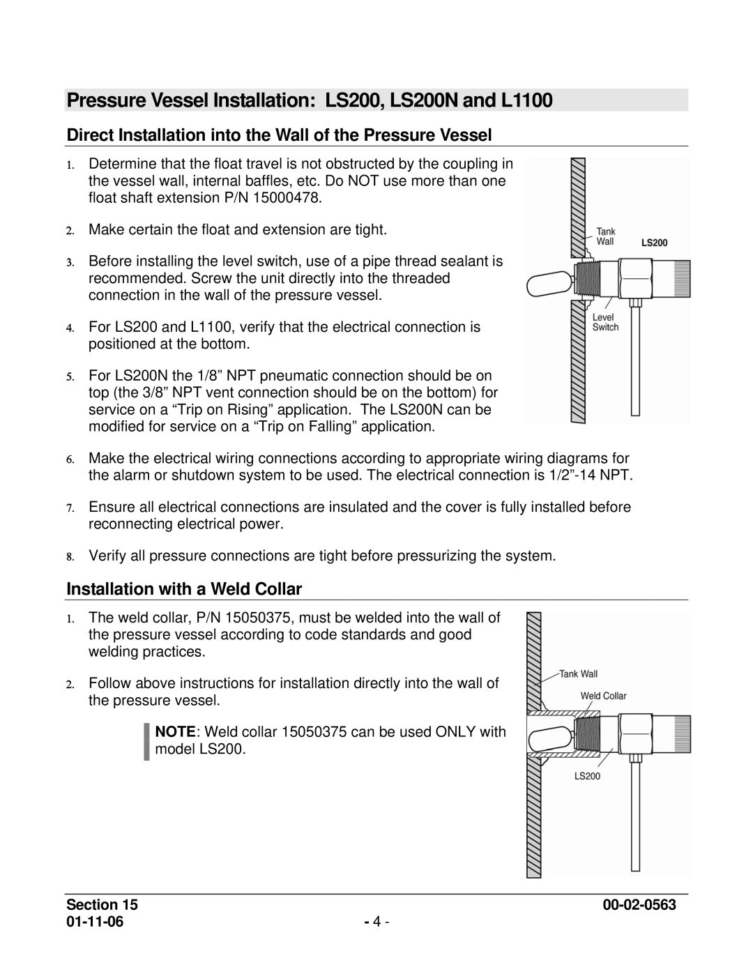
1.Determine that the float travel is not obstructed by the coupling in the vessel wall, internal baffles, etc. Do NOT use more than one float shaft extension P/N 15000478.
2.Make certain the float and extension are tight.
3.Before installing the level switch, use of a pipe thread sealant is recommended. Screw the unit directly into the threaded connection in the wall of the pressure vessel.
4.For LS200 and L1100, verify that the electrical connection is positioned at the bottom.
5.For LS200N the 1/8” NPT pneumatic connection should be on top (the 3/8” NPT vent connection should be on the bottom) for service on a “Trip on Rising” application. The LS200N can be modified for service on a “Trip on Falling” application.
6.Make the electrical wiring connections according to appropriate wiring diagrams for the alarm or shutdown system to be used. The electrical connection is
7.Ensure all electrical connections are insulated and the cover is fully installed before reconnecting electrical power.
8.Verify all pressure connections are tight before pressurizing the system.
Installation with a Weld Collar
1.The weld collar, P/N 15050375, must be welded into the wall of the pressure vessel according to code standards and good welding practices.
2.Follow above instructions for installation directly into the wall of the pressure vessel.
NOTE: Weld collar 15050375 can be used ONLY with model LS200.
Section 15 | |
- 4 - |