6-5 Wiring Options
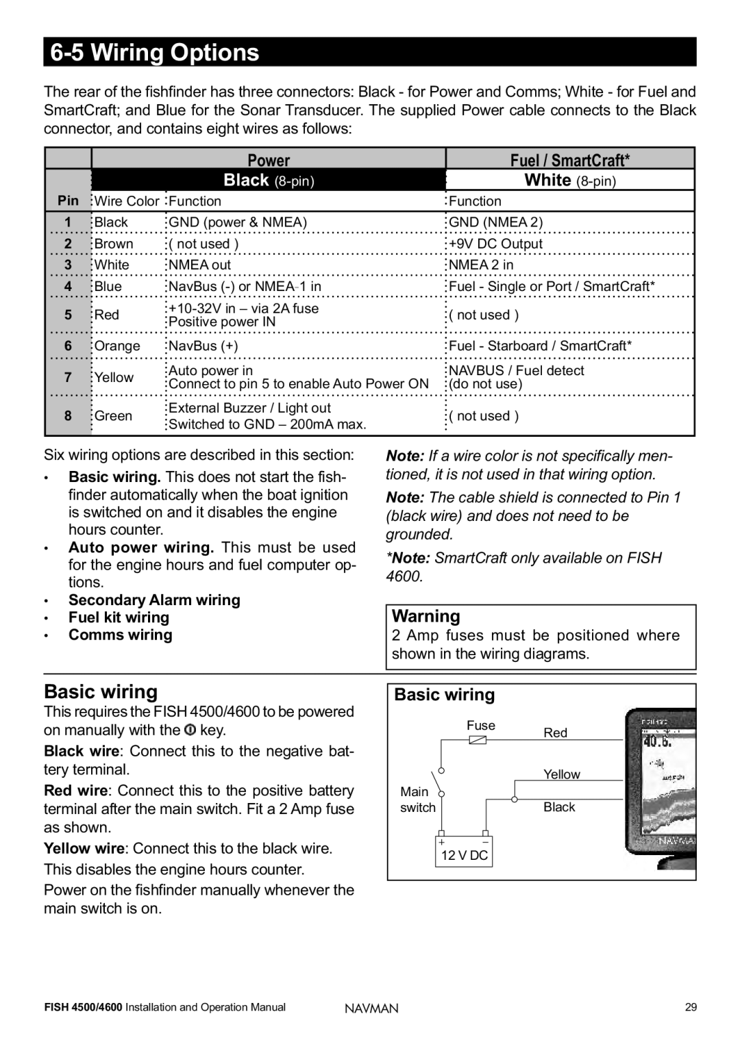
The rear of the fishfinder has three connectors: Black - for Power and Comms; White - for Fuel and SmartCraft; and Blue for the Sonar Transducer. The supplied Power cable connects to the Black connector, and contains eight wires as follows:
|
| Power | Fuel / SmartCraft* | |
|
| Black | White | |
Pin | Wire Color | Function | Function | |
1 | Black | GND (power & NMEA) | GND (NMEA 2) | |
2 | Brown | ( not used ) | +9V DC Output | |
3 | White | NMEA out | NMEA 2 in | |
4 | Blue | NavBus | Fuel - Single or Port / SmartCraft* | |
5 | Red | ( not used ) | ||
Positive power IN | ||||
|
|
| ||
6 | Orange | NavBus (+) | Fuel - Starboard / SmartCraft* | |
7 | Yellow | Auto power in | NAVBUS / Fuel detect | |
Connect to pin 5 to enable Auto Power ON | (do not use) | |||
|
| |||
8 | Green | External Buzzer / Light out | ( not used ) | |
Switched to GND – 200mA max. | ||||
|
|
| ||
|
|
|
|
Six wiring options are described in this section:
•Basic wiring. This does not start the fish- finder automatically when the boat ignition is switched on and it disables the engine hours counter.
•Auto power wiring. This must be used for the engine hours and fuel computer op- tions.
•Secondary Alarm wiring
•Fuel kit wiring
•Comms wiring
Note: If a wire color is not specifically men- tioned, it is not used in that wiring option.
Note: The cable shield is connected to Pin 1 (black wire) and does not need to be grounded.
*Note: SmartCraft only available on FISH 4600.
Warning
2 Amp fuses must be positioned where shown in the wiring diagrams.
Basic wiring
This requires the FISH 4500/4600 to be powered on manually with the ![]() key.
key.
Black wire: Connect this to the negative bat- tery terminal.
Red wire: Connect this to the positive battery terminal after the main switch. Fit a 2 Amp fuse as shown.
Yellow wire: Connect this to the black wire. This disables the engine hours counter. Power on the fishfinder manually whenever the main switch is on.
Basic wiring |
|
Fuse | Red |
| |
| Yellow |
Main |
|
switch | Black |
12 V DC |
|
FISH 4500/4600 Installation and Operation Manual | NAVMAN | 29 |
