Removing the display unit
The display unit can be removed after each use for protection against the environment or security reasons.
When removing the display unit, ensure that
the plugs left in the boat are not exposed to the elements. Push the attached dust covers over the exposed ends of the plugs. Keep the display unit in a dry clean place such as the optional Navman carry bag.
6-4 Power and transducer connections
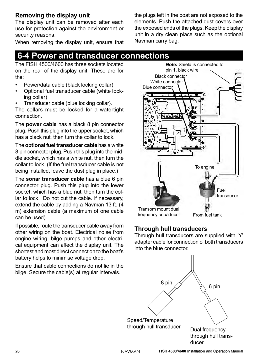
The FISH 4500/4600 has three sockets located on the rear of the display unit. These are for the:
•Power/data cable (black locking collar)
•Optional fuel transducer cable (white lock- ing collar)
•Transducer cable (blue locking collar). The collars must be locked for a watertight connection.
The power cable has a black 8 pin connector plug. Push this plug into the upper socket, which has a black nut, then turn the collar to lock.
The optional fuel transducer cable has a white
8pin connector plug. Push this plug into the mid- dle socket, which has a white nut, then turn the collar to lock. (If the fuel transducer cable is not being installed, leave the dust plug in place.)
The sonar transducer cable has a blue 6 pin connector plug. Push this plug into the lower socket, which has a blue nut, then turn the col- lar to lock. Do not cut the cable. If necessary, extend the cable by adding a Navman 13 ft. (4
m)extension cable (a maximum of one cable can be used).
If possible, route the transducer cable away from other wiring on the boat. Electrical noise from engine wiring, bilge pumps and other electri- cal equipment can affect the display unit. The shortest and most direct connection to the boat’s battery helps to minimise voltage drop.
Ensure that cable connections do not lie in the bilge. Secure the cable(s) at regular intervals.
Note: Shield is connected to pin 1, black wire
Black connector White connector
Blue connector
To engine
Fuel transducer
Transom mount dual |
|
frequency aquaducer | From fuel tank |
Through hull transducers
Through hull transducers are supplied with ‘Y’ adapter cable for connection of both transducers into the blue connector.
8 pin
![]() 6 pin
6 pin
Speed/Temperature
through hull transducer
Dual frequency through hull trans- ducer
28 | NAVMAN | FISH 4500/4600 Installation and Operation Manual |