LT265/LT245
Safety Cautions
Precautions
DOC Compliance Notice for Canada only
Important Safeguards
Installation
Important Information RF Interference for USA only
Iii
Important Information Fire and Shock Precautions
To replace the lamp, follow all instructions provided on
Important Information Lamp Replacement
Table of Contents
Maintenance
Introduction
Introduction
Registration card Limited warranty
Guarantee policy
Whats in the Box?
Introduction to the Projector
Features you’ll enjoy on the LT265/LT245
Introduction
Carrying the Projector
Part Names of the Projector
Introduction
Introduction Top Features
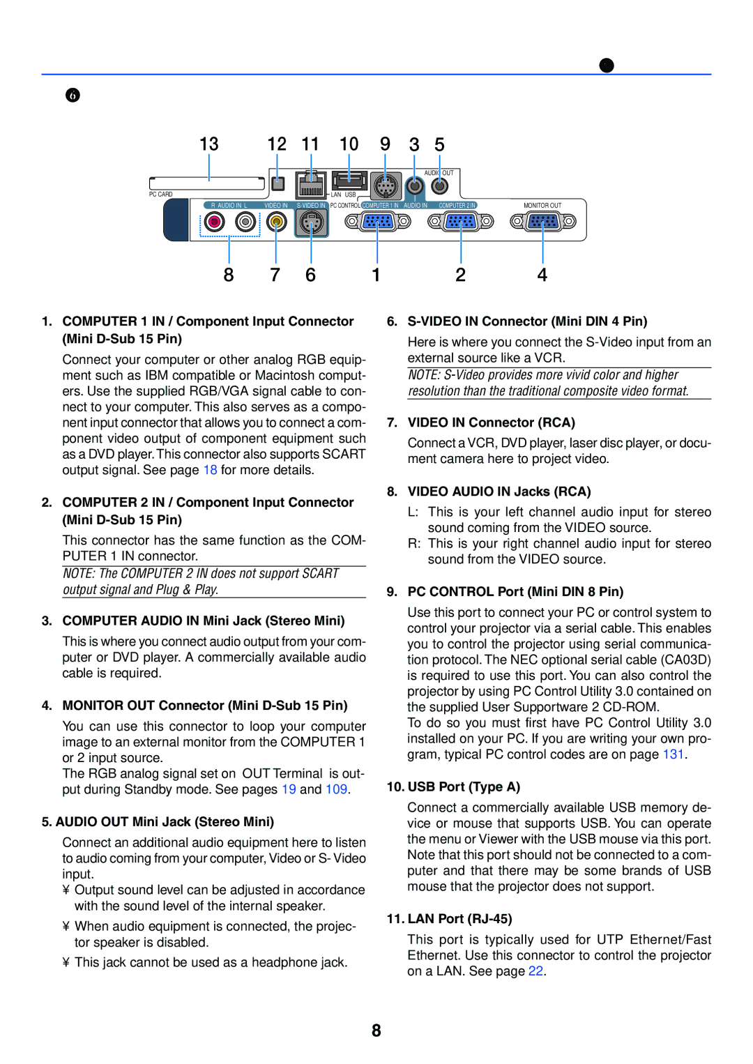
Introduction Terminal Panel Features
PC Card Eject Button
Press to eject a PC card partially
PC Card Slot
Part Names of the Remote Control
Video Button
Volume +/- Buttons
Select Button
Click Button
Introduction Battery Installation
Operating Range for Wireless Remote Control
Remote Control Precautions
Installation and Connections
Unit m/inch
Setting Up the Screen and the Projector
Installation and Connections
Selecting a Location
LT245
Installation and Connections Throw Distance and Screen Size
Distance Chart
LT265
Reflecting the Image
Turn off the power to your projector and computer
Making Connections
To connect to a PC or Macintosh, simply
Video equipment such as DVD player
To connect Scart output RGB
To do so
Installation and Connections Connecting an External Monitor
Cable not supplied
To make these connections, simply
Example of wired LAN connection
Installation and Connections Connecting to a Network
Projector control feature
Picture transmission feature
Access Point Wired LAN
Removing the PC Card
Inserting the PC Card
PC Card slot accepts Pcmcia Type II only
Installation and Connections PC Card Type
Page
Projecting an Image
Turning on the Projector
Projecting an Image Basic Operation
See page 123 for more details
Press the Enter button to execute the selection
To select a menu language, follow these steps
Detecting the Signal Automatically
Selecting a Source
Selecting from Source List
Adjust the Tilt Foot
Adjusting the Picture Size and Position
Projecting an Image Basic Operation Zoom
Focus
Use the Focus ring to obtain the best focus
You can also correct keystone distortion manually To do so
Correcting Keystone Distortion
Auto Keystone Correction
Manual Keystone Correction
Projecting an Image Basic Operation
Turning Up or Down Volume
Adjusting the Image Using Auto Adjust
Optimizing an RGB Image Automatically
Using the Laser Pointer
To turn off the projector
Preparation Make sure that the main power is turned off
Turning off the Projector
After Use
Convenient Features
Freezing a Picture
Using the Pointer
Convenient Features
Turning Off the Image and Sound
Enlarging and Moving a Picture
Getting Integrated Help
You can enlarge the area you want up to 400 percent
Using a USB Mouse
Operate the Menus using the USB mouse
Mouse Cursor
When connecting using the USB port
Using Remote Mouse Receiver
Connecting the remote mouse receiver to your computer
When operating a computer via the remote mouse receiver
Cornerstone
Confirmation screen is displayed
Adjustable ranges for 3D Reform are as follows
Making Freehand Drawings on a Projected Image ChalkBoard
Exit
On the remote control or projector cabinet
Preparations
Press the eject button to eject the card
Assigning a Keyword for the first time
Preventing Unauthorized Use of the Projector
Convenient Features
Convenient Features
Press the Power ON/STANDBY button
Convenient Features Checking If Security is enabled
Convenient Features Disabling the Security
Using a USB Memory Device or USB Memory Card Reader
Handling of the Address for Operation via a Browser
Operation Using an Http Browser
Overview
Preparation Before Use
Convenient Features Structure of the Http Server
Displays the remaining life of the lamp as a percentage
Switches to a LAN signal
Refresh Updates the display of the following conditions
Computer2
Meeting room Office
Disclaimer
Click OK Desktop Control Utility 1.0 starts
Convenient Features Operations on the Computer
Page
For example to stop a PowerPoint slideshow
Operations on the projector -Operating the desktop
Use to cut off communications with the computer
Exiting the desktop operation using the taskbar in Windows
Exiting the desktop operation using the Disconnect icon
Using the Viewer
Easy to use
Using the Viewer
Features
Making the Most out of the Viewer Function
Projecting slides Viewer
Operating the Viewer Function from the Projector playback
Using the Viewer Viewer Window Elements
Off
Using the Viewer Setting Option for Viewer
Play Mode
Auto
Viewing Digital Images
Using the Viewer Exiting Viewer
Using the Viewer Deleting Captured Images
To delete captured images
This completes deleting
To delete all the captured images
Changing Background Logo
Using On-Screen Menu
Using the Menus
Using On-Screen Menu
Changes are stored until you adjust it again
Menu tree
OUT Terminal Last, Computer1, Computer2 Tools
4800, 9600, 19200 Options Auto Adjust
Auto Start Off, On Power Management Fan Mode Auto, High
Last, Auto, Select Computer1/2, Video, S-Video, Viewer, LAN
Menu Elements
Viewer
Menu Descriptions & Functions Source
Computer 1
Video
Using On-Screen Menu Entry List
Entering the Currently Projected Signal into the Entry List
Using the Entry List
Lock
Using On-Screen Menu Entry Edit Command
Source Name
Input Terminal
Contrast
Menu Descriptions & Functions Adjust
Adjusts the brightness level or the back raster intensity
Basic Brightness
Light yellow
Using On-Screen Menu Hue
Using the Wall Color Correction Wall Color
Sharpness
Stretched to display in 169 aspect ratio
Left & Right stretched with black borders on top and bottom
Standard 169 aspect
Left and right stretched to display the true aspect
Using On-Screen Menu Controlling Volume Volume
Reset
Picture Management Preset
Using On-Screen Menu Detail Settings
Using On-Screen Menu
Using On-Screen Menu Selecting Signal Type Signal Type
Computer signal
This function reduces video noise Off Filter is removed
Adjusts the image location horizontally and vertically
This allows you to manually adjust Clock and Phase
Evident when part of your image appears to be shimmering
Use Phase only after the Clock is complete
Image to fit the full screen
Using On-Screen Menu Selecting Resolution Resolution
Select overscan percentage 0%, 5% and 10% for signal
Selecting Overscan Percentage Overscan
Selecting Color Matrix Color Matrix
Turning On/Off 3 Dimension Separation 3D Y/C Separation
Selecting Interlace or Deinterlace I/P Converter
Can be seen
Deinterlace Still
You can correct vertical distortion manually from the menu
Menu Descriptions & Functions Setup
Basic Selecting Keystone Mode Keystone
Changes will be saved even when you turn off the projector
This is the default setting 100% Brightness
Using On-Screen Menu Selecting Cornerstone Mode Cornerstone
Setting Lamp Mode to Normal or Eco Lamp Mode
Selecting Menu Mode Menu Mode
Top right corner of the screen
Using On-Screen Menu Selecting Menu Color Menu Color Select
Turning On / Off Source Display and Message Display Select
You can choose a color for the menu
Selecting a Color or Logo for Background Background
Security Disabling the Cabinet Buttons Cabinet Button
Menu can be turned off manually
Delete
To assign your password
To delete your password
Entry
Using On-Screen Menu Security
To register a PC card as a protect key
To delete PC card data you registered
You can adjust the vertical position between top and bottom
Selecting Aspect Ratio and Position for Screen Screen
Position of the image in these areas
To select a wireless LAN access point
Using On-Screen Menu LAN Mode
Setting LAN Mode
Hints on How to Set Up LAN Connection
Type in 12 numeric characters
100
Built-in
Profiles for LAN port RJ-45
Use this button to connect the projector to a network
101
PC Card
WEP. See the Advanced menu later on
Advanced menu Network Type required for wireless only
LAN network via an access point
102
Pared to use of 64-bit datalength encryption
WEP required for wireless only
103
Uses 64-bit datalength for secure transmission
Used
Using Software Keyboard to enter an encryption key
104
Domain
Mail
105
Selecting Communication Speed Communication Speed
Using On-Screen Menu Projector Name
Using Software Keyboard
106
Is selected
Enabling Power Management Power Management
107
Enabling Auto Start Auto Start
Using On-Screen Menu Enabling High Speed Fan Mode Fan Mode
Selecting Default Source Default Source Select
108
Using On-Screen Menu Selecting Signal Format Signal Select
Setting Monitor OUT Connector OUT Terminal
109
110
Selecting Projecting Pointer Icon Pointer
Using On-Screen Menu Using Off Timer Off Timer
Setting Mouse Pointer, Button and Sensitivity Mouse
111
Remaining Lamp Time % Lamp Hour Meter H Projector Usage H
Menu Descriptions & Functions Information
112
Usage Time
Using On-Screen Menu Source Page1
113
Source Page2
LAN PC Card
Using On-Screen Menu LAN Built-in
Indicates the MAC address of the optional wireless LAN card
114
Using On-Screen Menu LAN Wireless
115
Version
116
Menu Descriptions & Functions Reset
117
Maintenance
118
Cleaning the Cabinet
Cleaning the Lens
Maintenance
Replacing the Lamp
119
To replace the lamp
120
121
122
Appendix
Appendix
Troubleshooting
Indicator Messages
123
For more information contact your dealer
124
125
Electrical
Specifications
126
Optical
Mechanical
127
Cabinet Dimensions
128
Unit mm inch
129
Pin Assignments of D-Sub Computer 1/2 Input Connector
Mini D-Sub 15 Pin Connector
Pin No RGB Signal Analog YCbCr Signal
130
Compatible Input Signal List
Cable Connection
PC Control Codes and Cable Connection
131
PC Control Codes
132
Using Software Keyboard
Appendix PC Control Connector DIN-8P
To 0 and Characters Use to type in password or keyword
Video and Audio
Troubleshooting Check List
Power
133
Computer
Installation environment
Signal cable
134
135
TravelCare Guide
Asia and Middle East
136
Case of Credit Card Card No. w/Valid Date
137
Company & Name with signature
Date
138
Condition of your TravelCare Service Program