INSTALLATION PROCEDURE
Cable Lead Location
3.Cable Lead Location
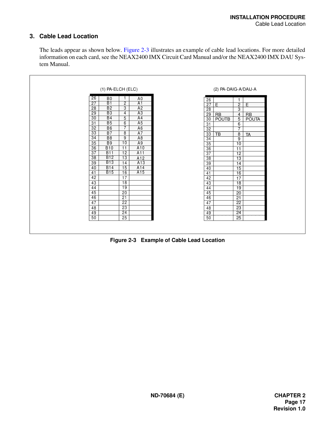
The leads appear as shown below. Figure
(1)
|
|
|
|
|
|
| 26 | B0 | 1 | A0 |
|
| 27 | B1 | 2 | A1 |
|
| 28 | B2 | 3 | A2 |
|
| 29 | B3 | 4 | A3 |
|
| 30 | B4 | 5 | A4 |
|
| 31 | B5 | 6 | A5 |
|
| 32 | B6 | 7 | A6 |
|
| 33 | B7 | 8 | A7 |
|
| 34 | B8 | 9 | A8 |
|
| 35 | B9 | 10 | A9 |
|
| 36 | B 10 | 11 | A 10 |
|
| 37 | B11 | 12 | A 11 |
|
| 38 | B12 | 13 | A 12 |
|
| 39 | B13 | 14 | A 13 |
|
| 40 | B14 | 15 | A 14 |
|
| 41 | B15 | 16 | A 15 |
|
| 42 |
| 17 |
|
|
| 43 |
| 18 |
|
|
| 44 |
| 19 |
|
|
| 45 |
| 20 |
|
|
| 46 |
| 21 |
|
|
| 47 |
| 22 |
|
|
| 48 |
| 23 |
|
|
| 49 |
| 24 |
|
|
| 50 |
| 25 |
|
|
(2)
|
|
|
|
|
|
26 |
| 1 |
|
| |
27 | E | 2 | E |
| |
28 |
| 3 |
|
| |
29 | RB | 4 | RB |
| |
30 | POUTB | 5 | POUTA |
| |
31 |
| 6 |
|
| |
32 |
| 7 |
|
| |
33 | TB | 8 | TA |
| |
34 |
| 9 |
|
| |
35 |
| 10 |
|
| |
36 |
| 11 |
|
| |
37 |
| 12 |
|
| |
38 |
| 13 |
|
| |
39 |
| 14 |
|
| |
40 |
| 15 |
|
| |
41 |
| 16 |
|
| |
42 |
| 17 |
|
| |
43 |
| 18 |
|
| |
44 |
| 19 |
|
| |
45 |
| 20 |
|
| |
46 |
| 21 |
|
| |
47 |
| 22 |
|
| |
48 |
| 23 |
|
| |
49 |
| 24 |
|
| |
50 |
| 25 |
|
| |
Figure 2-3 Example of Cable Lead Location
ND-70684 (E)CHAPTER 2
Page 17
