GS752TXS Smart Switch Hardware Installation Guide
Power
Link/Act Mode —
|
|
|
|
|
|
|
|
|
|
|
|
|
|
|
|
|
|
|
|
|
|
|
|
|
|
|
|
|
|
|
|
|
|
|
|
|
|
|
|
|
|
|
|
|
|
|
|
|
| GS752TXS | |
1 | 2 | 3 | 4 | 5 | 6 | 7 | 8 | 9 | 10 | 11 | 12 | 13 | 14 | 15 | 16 | 17 | 18 | 19 | 20 | 21 | 22 | 23 | 24 | 25 | 26 | 27 | 28 | 29 | 30 | 31 | 32 | 33 | 34 | 35 | 36 | 37 | 38 | 39 | 40 | 41 | 42 | 43 | 44 | 45 | 46 | 47 | 48 | 49F | 50F | 51F | 52F |
Fan |
| Green=Link at 1G |
|
|
|
|
|
|
|
|
|
|
|
|
|
|
|
|
|
|
|
| Yellow=Link at 10/ |
|
|
|
|
|
|
|
|
|
|
|
|
|
|
|
|
|
|
Stack |
| 100M |
|
|
|
|
|
|
|
|
|
|
|
|
|
|
|
|
|
|
Master | ID |
|
|
|
|
|
|
|
|
|
|
|
|
|
|
|
|
|
| |
|
|
|
|
|
|
|
|
|
|
|
|
|
|
|
|
|
|
|
|
|
|
|
|
|
|
|
|
|
|
|
|
|
|
|
|
|
|
|
|
|
|
Reset | Factory |
| ||||||||||||||||||
| Defaults |
|
| |||||||||||||||||
SFP |
+ |
Green=10GGreen=10GG LinkLink Yellow=1G |
Blink=ACTB |
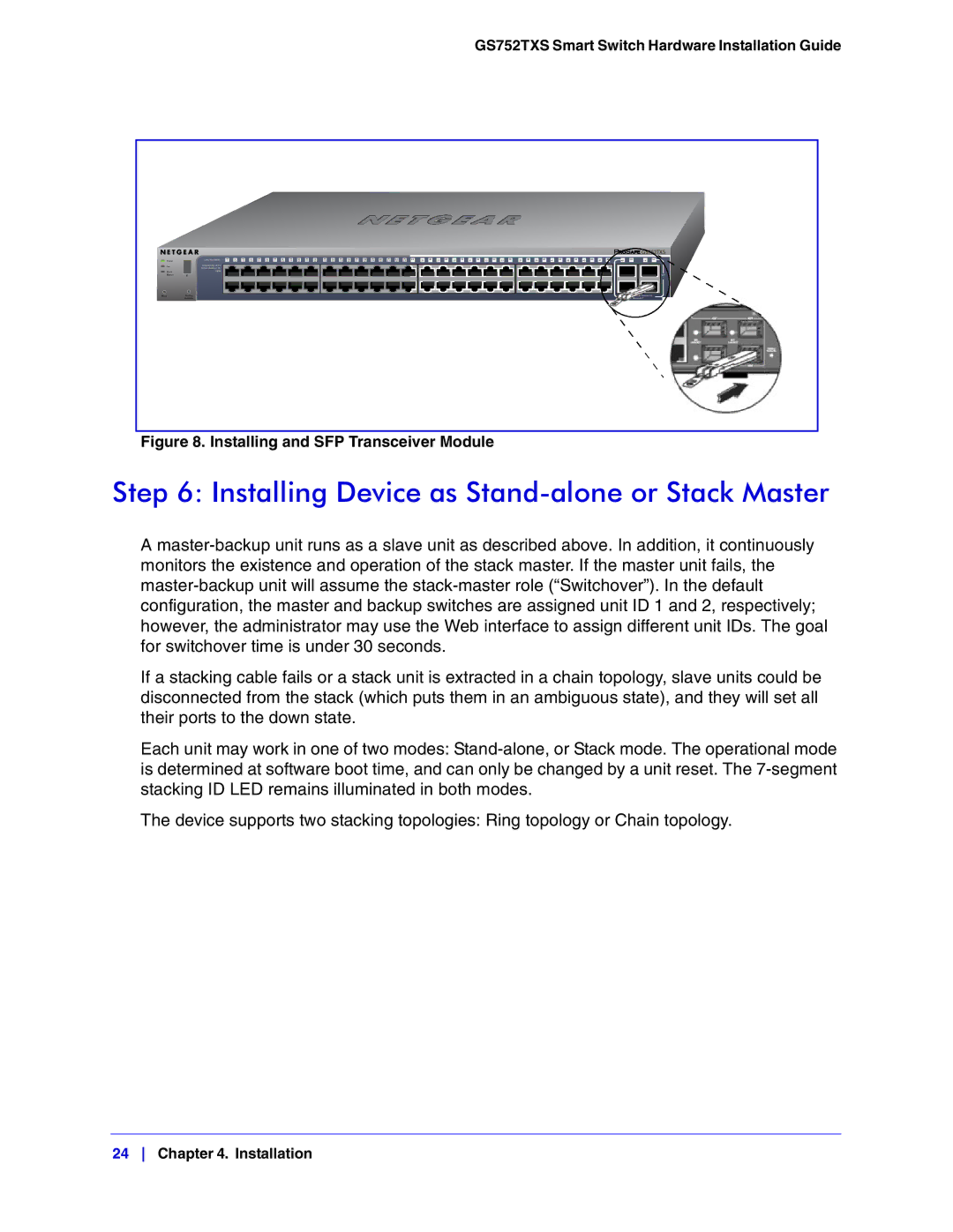
Figure 8. Installing and SFP Transceiver Module
Step 6: Installing Device as Stand-alone or Stack Master
A
If a stacking cable fails or a stack unit is extracted in a chain topology, slave units could be disconnected from the stack (which puts them in an ambiguous state), and they will set all their ports to the down state.
Each unit may work in one of two modes:
The device supports two stacking topologies: Ring topology or Chain topology.
24 Chapter 4. Installation