2. Physical Description | 2 |
|
This chapter describes the GS752TXS Smart Switch hardware features. Topics include:
•GS752TXS
•LED Designations
•Device Hardware Interfaces
GS752TXS Front-Panel and Back-Panel Configuration
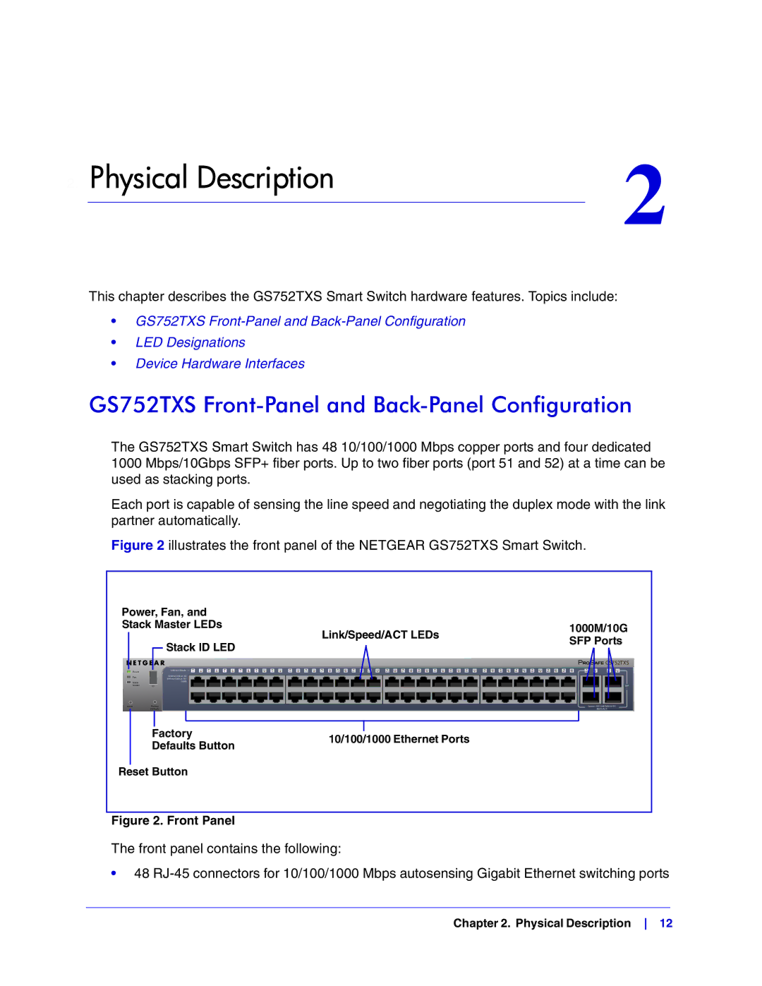
The GS752TXS Smart Switch has 48 10/100/1000 Mbps copper ports and four dedicated 1000 Mbps/10Gbps SFP+ fiber ports. Up to two fiber ports (port 51 and 52) at a time can be used as stacking ports.
Each port is capable of sensing the line speed and negotiating the duplex mode with the link partner automatically.
Figure 2 illustrates the front panel of the NETGEAR GS752TXS Smart Switch.
Power, Fan, and |
|
| ||
Stack Master LEDs | Link/Speed/ACT LEDs | 1000M/10G | ||
|
|
| ||
|
| Stack ID LED | SFP Ports | |
|
|
| ||
|
|
|
| |
| Power |
| Link/Act Mode — 1 | 2 | 3 | 4 | 5 | 6 | 7 | 8 | 9 | 10 | 11 | 12 | 13 | 14 | 15 | 16 | 17 | 18 | 19 | 20 | 21 | 22 | 23 | 24 | 25 | 26 | 27 | 28 | 29 | 30 | 31 | 32 | 33 | 34 | 35 | 36 | ||||||||||||||||||
| Fan |
| Green=Link at 1G |
|
|
|
|
|
|
|
|
|
|
|
|
|
|
|
|
|
|
|
|
|
|
|
|
|
|
|
|
|
|
|
|
|
|
|
|
|
|
|
|
|
|
|
|
|
|
|
|
|
|
|
|
|
|
|
| Yellow=Link at 10/ |
|
|
|
|
|
|
|
|
|
|
|
|
|
|
|
|
|
|
|
|
|
|
|
|
|
|
|
|
|
|
|
|
|
|
|
|
|
|
|
|
|
|
|
|
|
|
|
|
|
|
|
|
|
| Stack |
| 100M |
|
|
|
|
|
|
|
|
|
|
|
|
|
|
|
|
|
|
|
|
|
|
|
|
|
|
|
|
|
|
|
|
|
|
|
|
|
|
|
|
|
|
|
|
|
|
|
|
|
|
|
|
|
| Master | ID |
|
|
|
|
|
|
|
|
|
|
|
|
|
|
|
|
|
|
|
|
|
|
|
|
|
|
|
|
|
|
|
|
|
|
|
|
|
|
|
|
|
|
|
|
|
|
|
|
|
|
|
|
|
|
|
|
|
|
|
|
|
|
|
|
|
|
|
|
|
|
|
|
|
|
|
|
|
|
|
|
|
|
|
|
|
|
|
|
|
|
|
|
|
|
|
|
|
|
|
|
|
|
|
|
|
|
|
|
|
|
|
|
|
|
|
|
|
|
|
|
|
|
|
|
|
|
|
|
|
|
|
|
|
|
|
|
|
|
|
|
|
|
|
|
|
|
|
|
|
|
|
|
|
|
|
|
|
|
|
|
|
|
|
|
|
|
|
|
|
|
|
|
|
|
|
|
|
|
|
|
|
|
|
|
|
|
|
|
|
|
|
|
|
|
|
|
|
|
|
|
|
|
|
|
|
|
|
|
|
|
|
|
|
|
|
|
|
|
|
|
|
|
|
|
|
Reset | Factory |
|
|
|
|
|
|
|
|
|
|
|
|
|
|
|
|
|
|
|
|
|
|
|
|
|
|
|
|
|
|
|
|
|
|
|
|
|
|
|
|
|
|
|
|
|
|
|
|
|
|
|
|
| ||
|
| Defaults |
|
|
|
|
|
|
|
|
|
|
|
|
|
|
|
|
|
|
|
|
|
|
|
|
|
|
|
|
|
|
|
|
|
|
|
|
|
|
|
|
|
|
|
|
|
|
|
|
|
|
|
|
| |
|
|
|
|
|
|
|
|
|
|
|
|
|
| GS752TXS | |
37 | 38 | 39 | 40 | 41 | 42 | 43 | 44 | 45 | 46 | 47 | 48 | 49F | 50F | 51F | 52F |
|
|
|
|
|
|
|
|
|
|
|
|
|
|
| SFP |
|
|
|
|
|
|
|
|
|
|
|
|
|
|
| + |
|
|
|
|
|
|
|
|
|
|
|
|
| Green=10G Link Yellow=1G |
| |
|
|
|
|
|
|
|
|
|
|
|
|
|
| Blink=ACT |
|
|
|
|
|
| |
|
|
|
|
| |
Factory |
|
| |||
10/100/1000 Ethernet Ports | |||||
Defaults Button | |||||
|
| ||||
Reset Button |
|
| |||
Figure 2. Front Panel
The front panel contains the following:
•48
Chapter 2. Physical Description 12