GS752TXS Smart Switch Hardware Installation Guide
Power | Link/Act Mode — | 1 | 2 | 3 | 4 | 5 | 6 | 7 | 8 | 9 | 10 | 11 | 12 | 13 | 14 | 15 | 16 | 17 | 18 | 19 | 20 | 21 | 22 | 23 | 24 | 25 | 26 | 27 | 28 | 29 | 30 | 31 | 32 | 33 | 34 | 35 | 36 |
Fan | Green=Link at 1G |
|
|
|
|
|
|
|
|
|
|
|
|
|
|
|
|
|
|
|
|
|
|
|
|
|
|
|
|
|
|
|
|
|
|
|
|
Yellow=Link at 10/ |
|
|
|
|
|
|
|
|
|
|
|
|
|
|
|
|
|
|
|
|
|
|
|
|
|
|
|
|
|
|
|
|
|
|
|
| |
Stack | 100M |
|
|
|
|
|
|
|
|
|
|
|
|
|
|
|
|
|
|
|
|
|
|
|
|
|
|
|
|
|
|
|
|
|
|
|
|
Master | ID |
|
|
|
|
|
|
|
|
|
|
|
|
|
|
|
|
|
|
|
|
|
|
|
|
|
|
|
|
|
|
|
|
|
|
|
|
Reset | Factory |
| Defaults |
|
|
|
|
|
|
|
|
|
|
|
|
|
| GS752TXS | |
37 | 38 | 39 | 40 | 41 | 42 | 43 | 44 | 45 | 46 | 47 | 48 | 49F | 50F | 51F | 52F |
|
|
|
|
|
|
|
|
|
|
|
|
|
|
| SFP |
|
|
|
|
|
|
|
|
|
|
|
|
|
|
| + |
|
|
|
|
|
|
|
|
|
|
|
|
| Green=10G Link Yellow=1G |
| |
|
|
|
|
|
|
|
|
|
|
|
|
|
| Blink=ACT |
|
`![]()
`![]()
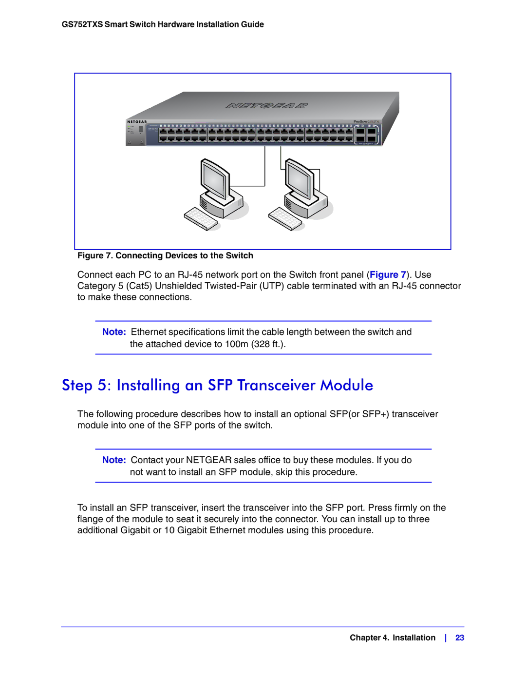
Figure 7. Connecting Devices to the Switch
Connect each PC to an
Note: Ethernet specifications limit the cable length between the switch and the attached device to 100m (328 ft.).
Step 5: Installing an SFP Transceiver Module
The following procedure describes how to install an optional SFP(or SFP+) transceiver module into one of the SFP ports of the switch.
Note: Contact your NETGEAR sales office to buy these modules. If you do not want to install an SFP module, skip this procedure.
To install an SFP transceiver, insert the transceiver into the SFP port. Press firmly on the flange of the module to seat it securely into the connector. You can install up to three additional Gigabit or 10 Gigabit Ethernet modules using this procedure.
Chapter 4. Installation 23