GS752TXS Smart Switch Hardware Installation Guide
•Four dedicated 1000 Mbps/10Gbps SFP+ Gigabit Ethernet switching ports. Up to two of these ports (ports 51 and 52) can alternatively be used as stacking ports.
•Reset button to restart the device
•Recessed default reset button to restore the device back to the factory defaults
•Link, Speed, and Activity LEDs for each port
•Power, Fan Status, Stack Master, and Stack ID LEDs
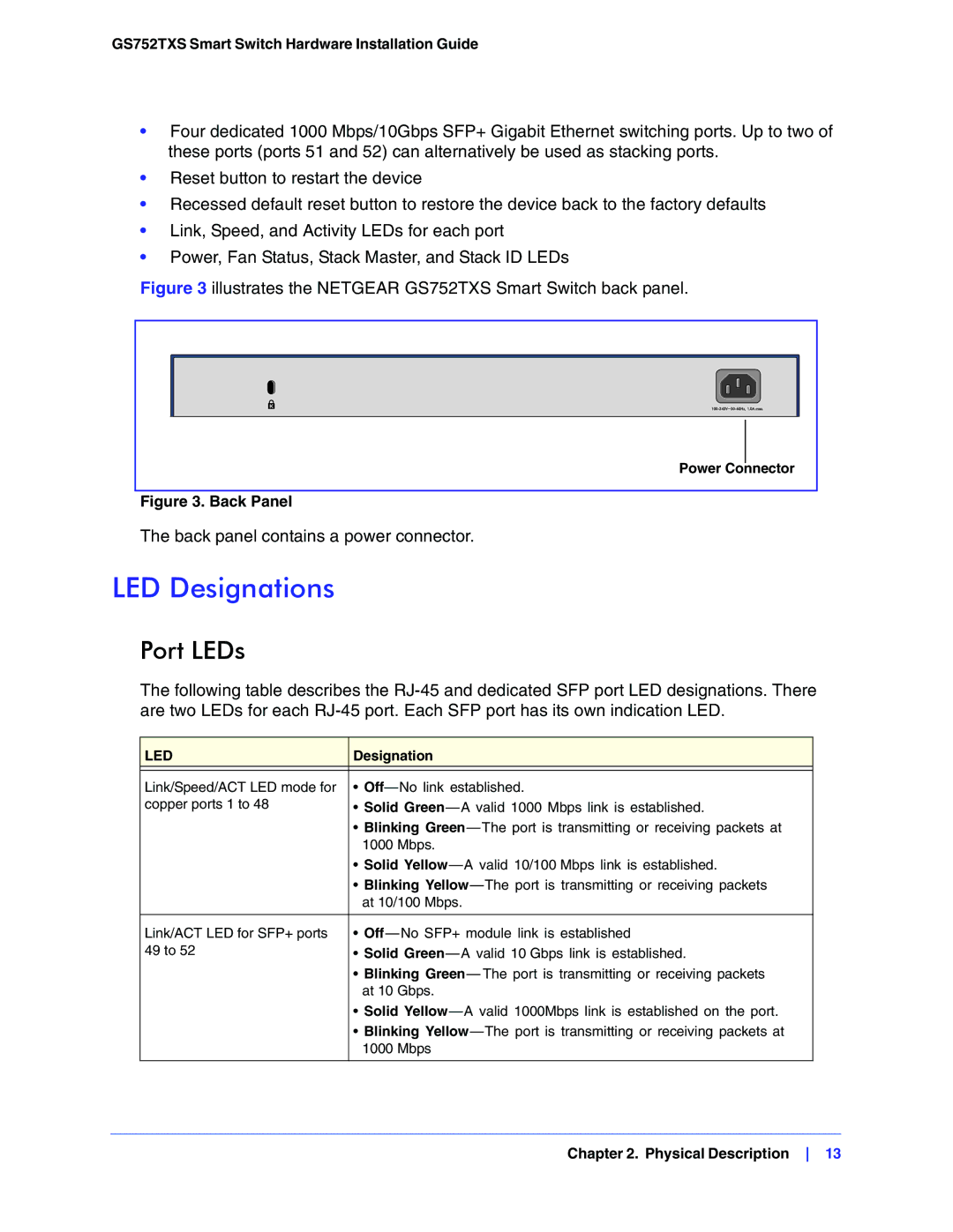
Figure 3 illustrates the NETGEAR GS752TXS Smart Switch back panel.
Power Connector
Figure 3. Back Panel
The back panel contains a power connector.
LED Designations
Port LEDs
The following table describes the
LED | Designation |
|
|
Link/Speed/ACT LED mode for | • |
copper ports 1 to 48 | • Solid |
| • Blinking |
| 1000 Mbps. |
| • Solid |
| • Blinking |
| at 10/100 Mbps. |
|
|
Link/ACT LED for SFP+ ports | • |
49 to 52 | • Solid |
| • Blinking Green— The port is transmitting or receiving packets |
| at 10 Gbps. |
| • Solid |
| • Blinking |
| 1000 Mbps |
|
|
Chapter 2. Physical Description 13