NTI UNIMUX SERIES USB KVM SWITCH
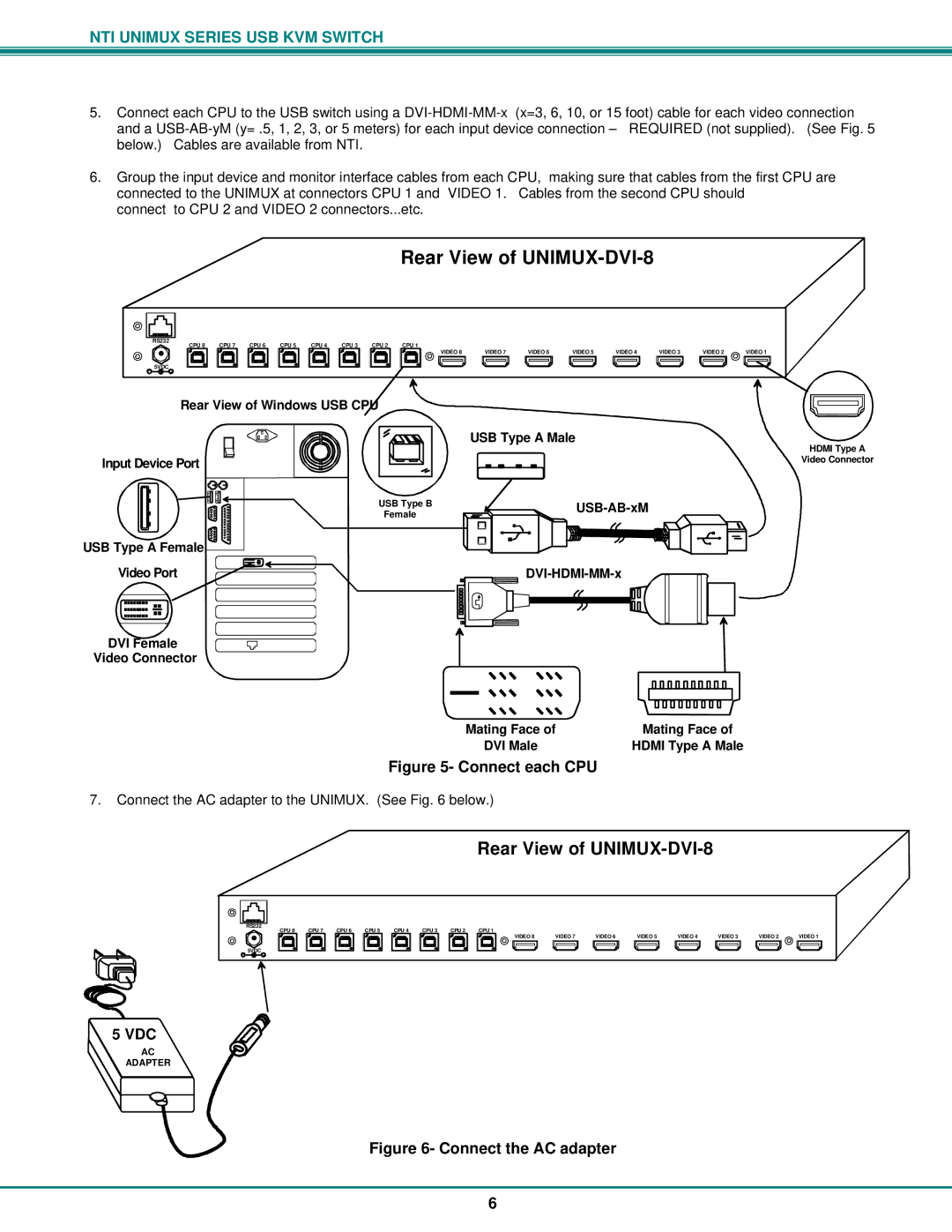
5.Connect each CPU to the USB switch using a
and a
6.Group the input device and monitor interface cables from each CPU, making sure that cables from the first CPU are connected to the UNIMUX at connectors CPU 1 and VIDEO 1. Cables from the second CPU should
connect to CPU 2 and VIDEO 2 connectors...etc.
Rear View of UNIMUX-DVI-8
|
|
|
|
|
|
|
|
|
|
|
|
|
|
|
|
|
|
|
|
|
|
|
|
|
RS232 | CPU 8 | CPU 7 | CPU 6 | CPU 5 |
| CPU 4 | CPU 3 | CPU 2 | CPU 1 |
|
|
|
|
|
|
| ||||||||
|
|
|
|
|
|
|
|
|
| |||||||||||||||
- 5VDC + |
|
|
|
|
|
|
|
|
|
|
|
|
|
|
| VIDEO 8 | VIDEO 7 | VIDEO 6 | VIDEO 5 | VIDEO 4 | VIDEO 3 | VIDEO 2 | VIDEO 1 | |
|
|
|
|
|
|
|
|
|
|
|
|
|
|
|
|
|
|
|
|
|
|
| ||
|
|
|
|
|
|
|
|
|
|
|
|
|
|
|
|
|
|
|
|
|
|
| ||
Rear View of Windows USB
|
|
|
|
| USB Type A Male | ||||||||
|
|
|
|
| |||||||||
|
|
|
|
|
|
|
|
|
|
|
|
|
|
Input Device Port |
|
|
|
|
|
|
|
|
|
|
| ||
|
|
|
|
|
|
|
|
|
|
| |||
|
|
|
|
|
|
|
|
|
|
|
|
|
|
|
| USB Type B |
|
|
|
|
|
|
|
| |||
|
|
| Female |
|
|
|
|
|
|
|
| ||
|
|
|
|
|
|
|
|
|
|
|
| ||
|
|
|
|
|
|
|
|
|
|
|
|
|
|
|
|
|
|
|
|
|
|
|
|
|
|
|
|
USB Type A Female
Video Port | ||||
|
|
|
|
|
|
|
|
|
|
|
|
|
|
|
DVI Female
Video Connector
Mating Face of | Mating Face of |
DVI Male | HDMI Type A Male |
Figure 5- Connect each CPU
7.Connect the AC adapter to the UNIMUX. (See Fig. 6 below.)
HDMI Type A
Video Connector
Rear View of
RS232 | CPU 8 | CPU 7 | CPU 6 | CPU 5 | CPU 4 | CPU 3 | CPU 2 | CPU 1 |
|
- 5VDC +
VIDEO 8 | VIDEO 7 | VIDEO 6 | VIDEO 5 | VIDEO 4 | VIDEO 3 | VIDEO 2 | VIDEO 1 |
5 VDC
AC
ADAPTER
Figure 6- Connect the AC adapter
6