Note: Position the current transformers with the dot or HI side CT marking toward the generator set.
Note: Only generator sets equipped with AC meter controllers and/or safeguard circuit breakers require CTs.
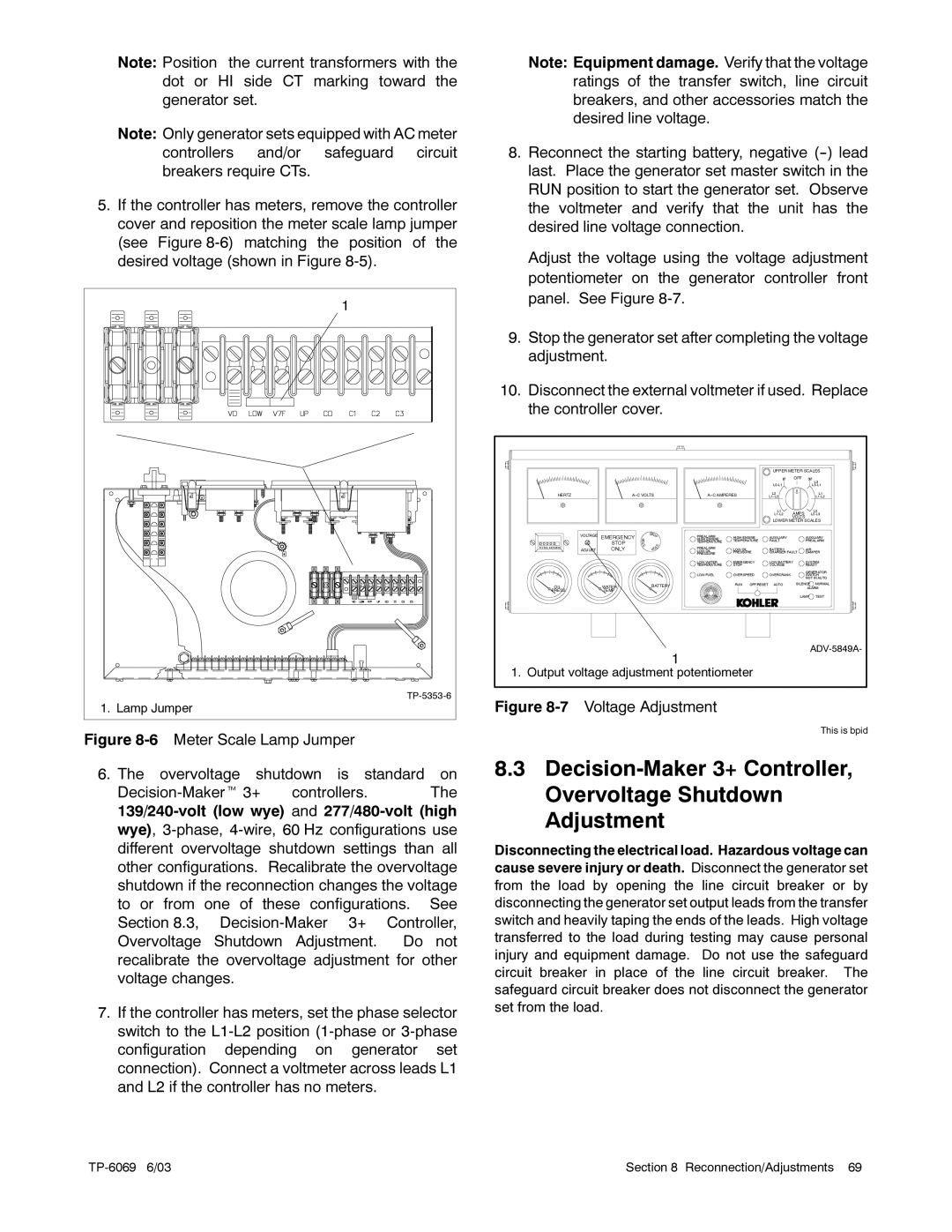
5.If the controller has meters, remove the controller cover and reposition the meter scale lamp jumper (see Figure
1
1. Lamp Jumper
Figure 8-6 Meter Scale Lamp Jumper
6. The overvoltage shutdown is standard on
Decision-Makert 3+ controllers. The 139/240-volt (low wye) and 277/480-volt (high wye), 3-phase, 4-wire, 60 Hz configurations use different overvoltage shutdown settings than all other configurations. Recalibrate the overvoltage shutdown if the reconnection changes the voltage to or from one of these configurations. See Section 8.3, Decision-Maker 3+ Controller, Overvoltage Shutdown Adjustment. Do not recalibrate the overvoltage adjustment for other voltage changes.
7.If the controller has meters, set the phase selector switch to the L1-L2 position (1-phase or 3-phase configuration depending on generator set connection). Connect a voltmeter across leads L1 and L2 if the controller has no meters.
Note: Equipment damage. Verify that the voltage ratings of the transfer switch, line circuit breakers, and other accessories match the desired line voltage.
8.Reconnect the starting battery, negative (--) lead last. Place the generator set master switch in the RUN position to start the generator set. Observe the voltmeter and verify that the unit has the desired line voltage connection.
Adjust the voltage using the voltage adjustment potentiometer on the generator controller front panel. See Figure 8-7.
9.Stop the generator set after completing the voltage adjustment.
10.Disconnect the external voltmeter if used. Replace the controller cover.
|
|
|
|
|
| UPPER METER SCALES | |||
|
|
|
|
|
| 1 | OFF | 3 |
|
|
|
|
|
|
|
|
|
| L3 |
|
|
|
|
|
|
|
| ||
HERTZ |
|
| L2 |
|
| L1 | |||
|
|
|
| ||||||
|
|
|
|
|
| L1 | AMPS |
| L2 |
|
|
|
|
|
|
| |||
|
|
|
|
|
|
| VOLTS |
|
|
|
|
|
|
|
| LOWER METER SCALES | |||
VOLTAGE |
| S | PREALARM |
|
|
|
|
|
|
EMERGENCY | HIGH ENGINE | AUXILIARY |
| AUXILIARY | |||||
| HIGH ENGINE |
| |||||||
0 0 0 0 0 | STOP | O | TEMPERATURE | TEMPERATURE | FAULT |
| PREALARM | ||
TOTAL HOURS | ONLY |
| PREALARM | LOW OIL |
| BATTERY |
| AIR | |
ADJUST |
| LOW OIL |
|
| |||||
|
|
| PRESSURE | PRESSURE | CHARGER FAULT | DAMPER | |||
|
|
| LOW WATER | EMERGENCY | LOW BATTERY | SYSTEM | |||
|
|
| TEMPERATURE | STOP |
| VOLTAGE |
| READY | |
|
|
|
|
|
|
|
| GENERATOR | |
|
|
| LOW FUEL | OVERSPEED | OVERCRANK |
| SWITCH | ||
|
|
|
|
|
|
|
| NOT IN AUTO | |
|
| BATTERY |
| RUN | OFF/RESET | AUTO | SILENCE | NORMAL | |
OIL | WATER |
|
|
|
|
|
| ALARM | |
PRESS | TEMP |
|
|
|
|
|
|
|
|
|
|
|
|
|
|
| LAMP | TEST | |
|
|
| 1 |
|
|
|
| ||
|
|
|
|
|
|
|
|
| |
1. Output voltage adjustment potentiometer |
|
|
|
| |||||
Figure 8-7 Voltage Adjustment
This is bpid
8.3
Disconnecting the electrical load. Hazardous voltage can cause severe injury or death. Disconnect the generator set from the load by opening the line circuit breaker or by disconnecting the generator set output leads from the transfer switch and heavily taping the ends of the leads. High voltage transferred to the load during testing may cause personal injury and equipment damage. Do not use the safeguard circuit breaker in place of the line circuit breaker. The safeguard circuit breaker does not disconnect the generator set from the load.
Section 8 Reconnection/Adjustments 69 |