8.1.3200--240-Volt Configurations
The
L0 (Neutral)
|
|
|
|
| L0 |
|
|
| Ground | GRD. | |
|
|
|
| ||
|
|
| Load |
| L1 |
|
|
|
|
| |
|
|
| Side |
|
|
|
| Line | |||
|
| Side | Circuit |
| |
|
|
|
| Breaker |
|
|
|
|
| Tape to insulate | |
|
|
|
| from ground |
|
4 | 3 | 2 | 1 | ||
|
|
|
| ||
Stator Leads | 2 Wire |
| |||
|
|
| 60 Hz | 50 Hz |
|
| |||||
Figure 8-4 200--220--240-Volt, 2-Wire Configuration
8.2 Twelve-Lead Reconnection
The reconnection procedure details voltage reconnections only. If the generator set requires frequency changes, adjust the governor and voltage
regulator. See the generator set service manual for information regarding frequency adjustment.
The following information illustrates the reconnection of
Reconnect the stator leads of the generator set to change output phase or voltage. Refer to the following procedure and connection schematics. Follow all safety precautions at the front of this manual and in the text during the reconnection procedure.
NOTICE
Voltage reconnection. Affix a notice to the generator set after reconnecting the set to a voltage different from the voltage on the nameplate. Order voltage reconnection decal 246242 from an authorized service distributor/dealer.
1.Place the generator start/stop switch in the STOP position.
2.Disconnect generator set engine starting battery, negative
3.Disconnect power to battery charger, if equipped.
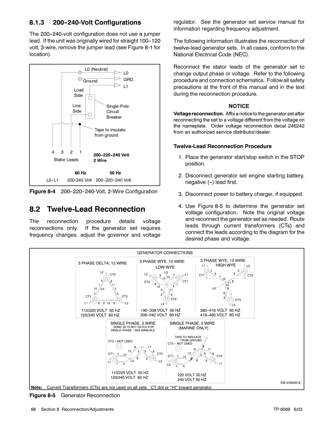
4.Use Figure
Note: Current Transformers (CTs) are not used on all sets. CT dot or “HI” toward generator.
Figure 8-5 Generator Reconnection
68 Section 8 Reconnection/Adjustments |