Stabilizer Potentiometer (Pot) fine tunes the regulator circuitry to reduce light flicker.
Voltage Adjustment Pot adjusts the generator voltage output within the range of approximately 100 to 130 volts.
Volts/Hz Pot determines the engine speed (Hz) at which the generator output voltage begins to drop.
Note: The volts/Hz adjustment does not apply to the following models:
Model
4/6.5/8/8.5/9EFOZ
5/8/9/10EOZ
Note: On these models, turn the volts/Hz adjustment pot full counterclockwise to stop and seal. No further volts/Hz adjustments are required.
Note: For optimum results, apply full load for voltage regulator adjustment.
Voltage Regulator Adjustment Procedure
1.With the generator set off, turn the remote rheostat, if equipped, to the midpoint.
2.Turn the voltage, volts/Hz, and stability pots fully counterclockwise.
3.Connect the voltmeter and frequency meter to the AC circuit or an electrical outlet.
4.Start the generator set.
5.Rotate the voltage adjustment pot clockwise to increase the voltage (counterclockwise to decrease voltage) to achieve the desired output voltage.
6.Rotate the stability pot clockwise to minimize light flicker.
7.Readjust the voltage adjustment pot if necessary.
8.Adjust the engine speed to the desired
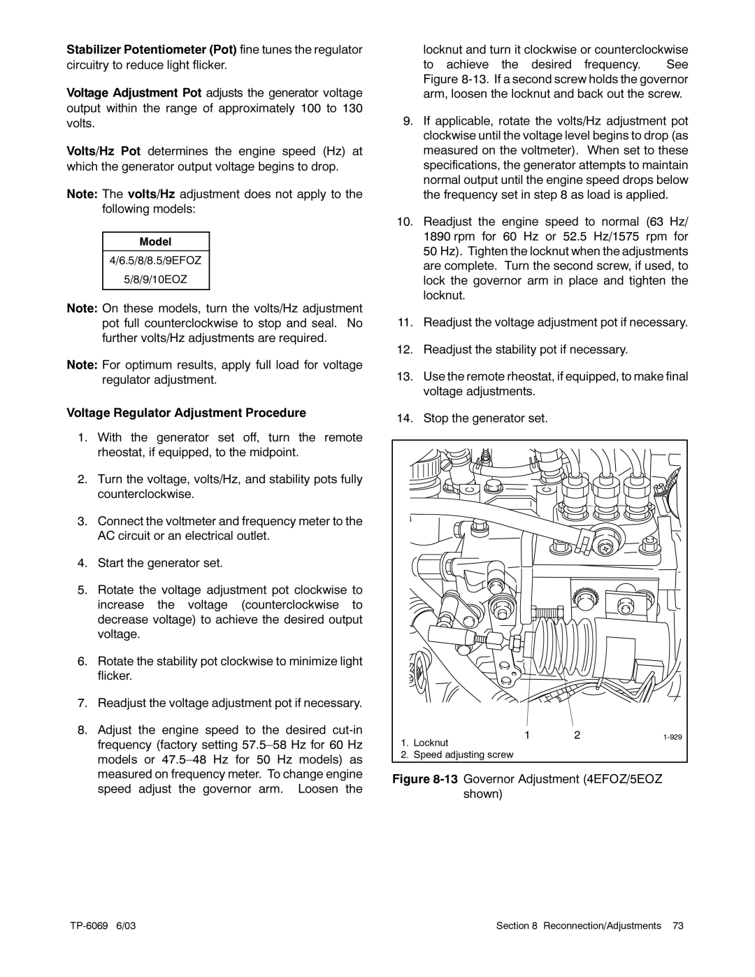
locknut and turn it clockwise or counterclockwise to achieve the desired frequency. See Figure
9.If applicable, rotate the volts/Hz adjustment pot clockwise until the voltage level begins to drop (as measured on the voltmeter). When set to these specifications, the generator attempts to maintain normal output until the engine speed drops below the frequency set in step 8 as load is applied.
10.Readjust the engine speed to normal (63 Hz/ 1890 rpm for 60 Hz or 52.5 Hz/1575 rpm for 50 Hz). Tighten the locknut when the adjustments are complete. Turn the second screw, if used, to lock the governor arm in place and tighten the locknut.
11.Readjust the voltage adjustment pot if necessary.
12.Readjust the stability pot if necessary.
13.Use the remote rheostat, if equipped, to make final voltage adjustments.
14.Stop the generator set.
1. | 1 | 2 | |
Locknut |
|
| |
2. | Speed adjusting screw |
|
|
Figure 8-13 Governor Adjustment (4EFOZ/5EOZ shown)
Section 8 Reconnection/Adjustments 73 |