Kraus Naimler/American Solenoid
L1 ![]()
![]()
![]() L1
L1
3 2 4 1
L2 |
|
|
| L2 |
To Generator 7 | 6 | 8 | 5 | To Shore |
Set |
|
|
| Power |
|
|
|
| |
L3 |
|
|
| L3 |
11 | 10 | 12 | 9 |
|
L0 |
|
|
| L0 |
15 | 14 | 16 | 13 |
|
L1 L2 | L3 | L0 |
|
|
To Load |
|
| ||
|
|
|
| |
Figure 8-10 Marine Manual (Ship-to-Shore) Transfer Switch, continued
8.4Voltage Regulator Adjustment (4-27EFOZ and 5-32EOZ Models)
WARNING
Hazardous voltage. Moving rotor.
Can cause severe injury or death.
Operate the generator set only when all guards and electrical enclosures are in place.
Testing the voltage regulator. Hazardous voltage can cause severe injury or death. High voltage is present at the voltage regulator heat sink. To prevent electrical shock do not touch the voltage regulator heat sink when testing the voltage regulator.
(PowerBoostt, PowerBoostt III, and PowerBoostt V voltage regulator models only)
The voltage regulator is typically located in the controller. Adjustments are possible without removing the voltage regulator. The voltage regulator adjustment procedure applies to both the PowerBoost IIIE (Figure
Note: Broadrange generator sets. The following adjustment procedure is for readjustment of the voltage regulator and governor for broadrange generator sets with mechanical governors.
Note: Special tool. Frequency meter 50/60 Hz.
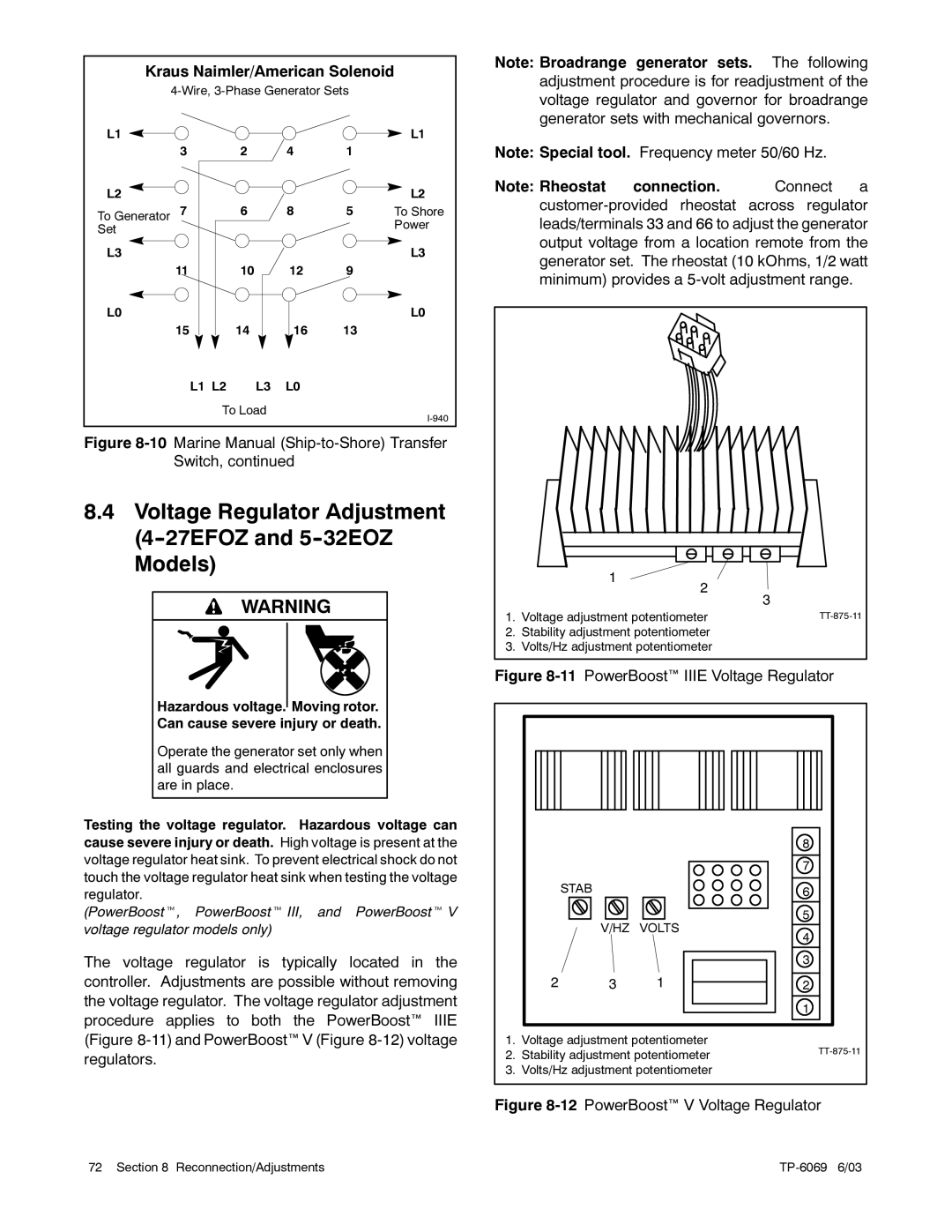
Note: Rheostat connection. Connect a
1
2
3
1. Voltage adjustment potentiometer |
2.Stability adjustment potentiometer
3.Volts/Hz adjustment potentiometer
Figure 8-11 PowerBoost IIIE Voltage Regulator
|
|
| 8 |
|
|
| 7 |
| STAB |
| 6 |
|
|
| |
|
|
| 5 |
| V/HZ | VOLTS | 4 |
|
|
| |
|
|
| 3 |
2 | 3 | 1 | 2 |
|
|
| 1 |
1. Voltage adjustment potentiometer
2. Stability adjustment potentiometerTT-875-11
3. Volts/Hz adjustment potentiometer
Figure 8-12 PowerBoost V Voltage Regulator
72 Section 8 Reconnection/Adjustments |