NTI XTENDEX Extenders
Plug-in and Boot Up
1.Plug the power cord from the monitor into the power outlet.
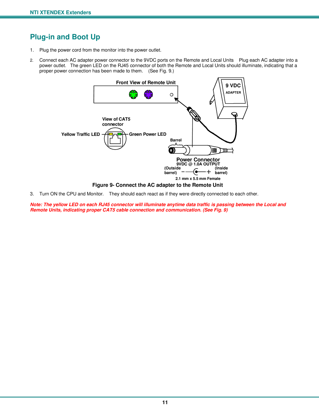
2. Connect each AC adapter power connector to the 9VDC ports on the Remote and Local Units Plug each AC adapter into a power outlet. The green LED on the RJ45 connector of both the Remote and Local Units should illuminate, indicating that a proper power connection has been made to them. (See Fig. 9.)
Front View of Remote Unit | 9 VDC | ||||
|
|
|
|
| |
|
|
|
|
| Adapter |
|
|
|
|
| ADAPTER |
|
|
|
|
| |
| View of CAT5 | ||||||
| connector | ||||||
Yellow Traffic LED |
|
|
|
|
|
| Green Power LED |
|
|
|
|
|
| ||
|
|
|
|
|
| ||
|
|
|
|
|
| ||
|
|
|
|
|
|
| Barrel |
|
|
|
|
|
|
|
|
Power Connector
9VDC @ 1.0A OUTPUT
(Outside | (Inside |
barrel) | barrel) |
2.1 mm x 5.5 mm Female
Figure 9- Connect the AC adapter to the Remote Unit
3.Turn ON the CPU and Monitor. They should each react as if they were directly connected to each other.
Note: The yellow LED on each RJ45 connector will illuminate anytime data traffic is passing between the Local and Remote Units, indicating proper CAT5 cable connection and communication. (See Fig. 9)
11