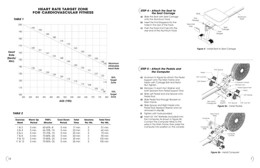
HEART RATE TARGET ZONE
FOR CARDIOVASCULAR FITNESS
STEP 4 – Attach the Seat to the Seat Carriage
a) Slide the Seat with Seat Carriage |
Seat
Aluminum
TABLE 1
200
190
180
170
Heart 160 Rate
(Beats/
195 |
| |
190 |
| |
185 |
| |
180 |
| |
175 |
| |
| 170 | |
165 | 165 | |
161 | 160 | |
157 | ||
155 | ||
153 | ||
148 | 150 |
| onto the Aluminum Track. |
b) | Insert the End Stoppers into the |
| holes in the rear of the Track. |
c) | Push the Track End Cap into the |
| rear end of the Aluminum Track. |
EndTrack Stopper
Track End
Cap
Seat
Carriage
End
Stopper
Figure 4 - Install Seat to Seat Carriage
Min)
150
140
130
120
110
100
20
|
|
|
|
|
| 144 |
|
|
|
| 145 | Maximum | |
|
|
|
|
|
|
| 140 |
|
|
|
| 140 | |
136 |
|
|
|
|
|
| 136 |
|
|
|
| Attainable | |
133 |
|
|
|
|
|
| 131 |
|
|
| Heart Rate | ||
|
| 129 |
|
|
|
|
|
|
|
|
| ||
|
|
|
|
|
|
|
|
| 127 |
|
|
| |
|
|
| 129 |
|
|
|
|
|
| 123 |
| ||
|
|
|
| 129 |
|
|
|
|
|
| |||
|
|
|
|
|
|
|
|
|
| 85% | |||
|
|
|
|
| 119 |
|
|
|
|
|
| ||
|
|
|
|
|
|
|
|
|
|
|
| ||
|
|
|
|
|
| 115 |
|
|
|
|
| Target | |
|
|
|
|
|
|
|
|
|
|
| 119 | ||
|
|
|
|
|
|
|
|
|
|
| Zone | ||
|
|
|
|
|
|
|
| 112 | 108 |
|
| ||
|
|
|
|
|
|
|
|
|
|
|
| ||
|
|
|
|
|
|
|
|
|
|
|
|
| |
|
|
|
|
|
|
|
|
|
| 105 | 101 |
| |
|
|
|
|
|
|
|
|
|
|
| 70% | ||
|
|
|
|
|
|
|
|
|
|
|
| 98 | |
|
|
|
|
|
|
|
|
|
|
|
|
| Target |
25 | 30 | 35 | 40 | 45 | 50 | 55 | 60 | 65 | 70 |
| 75 | 80 | Zone |
AGE (YRS)
STEP 5 – Attach the Pedals and
the Computer
a) As shown in Figure 5a attach the Pedal |
Support onto the Main Frame and |
fasten with Carriage Bolt and Nylon |
Nut. Tighten. |
b) Remove (1) each Nut, Washer and |
both Spacers from Pedal Support Rod. |
c) Slide Left Pedal and one Spacer onto |
Pedal Rod. |
d) Slide Pedal Rod through Bracket on |
Main Frame. |
e) Slide Spacer and Right Pedal onto |
Pedal Rod. Replace Washer and nut |
removed in step b). |
PVC Spacer
Pedal |
|
| |
3/8” Lock Nut |
|
| |
3/8” Washer | Computer Console | ||
| |||
| M8 Nylon Nut | ||
|
| Pedal Support Rod | |
|
| Pedal | |
|
| 3/8” Washer | |
M8 x 35mm | Pedal |
| |
Support PVC Spacer | 3/8” Lock Nut | ||
Carriage Bolt | |||
Figure 5a - Install Pedals
TABLE 2
Exercise | Warm Up | THR% | Cool Down | Total | Sessions | Total Time | |
Week | Period | Minutes | Period | Time | Per Wk. | Per Wk. | |
|
|
|
|
|
|
|
|
1 | & 2 | 5 min | 5 min | 17 min | 3 | 51 min | |
3 | & 4 | 5 min | 5 min | 20 min | 3 | 60 min | |
5 | & 6 | 5 min | 5 min | 25 min | 3 | 75 min | |
7 | & 8 | 5 min | 5 min | 30 min | 3 | 90 min | |
9 | & 10 | 5 min | 5 min | 35 min | 3 | 105 min | |
11 | & 12 | 5 min | 5 min | 35 min | 3 | 105 min | |
f) | Tighten with tools provided. |
g) | Insert (2) “AA” Batteries (included) into |
| the Computer. As shown in Figure 5b |
| Connect the Computer Wires to the |
| wires in the Main Frame, then press the |
| Computer into position on the console. |
Main Frame
Wires
Computer
Computer
Wires
Computer
Console
Figure 5b - Install Computer
14 | 7 |
