INSTALLATION
VENT ASSEMBLY
There are two basic types of installations approved with your model DV23ZC appliance. These are: Horizontal termination (See Figure 5)
Vertical termination (See Figure 10)
When planning your installation, refer to Figure 3 to ensure the length of your vent falls into the limits specified in Figure 3. Also consult page 9, “Exterior Vent Locations and Restrictions” regarding the placement of the vent terminal.
HORIZONTAL TERMINATION
1.Set the gas appliance in its desired location. Check to determine if wall studs or roof rafters are in the way when the venting system is attached. If this is the case, you may want to adjust the location of the appliance.
2.
3.Use only
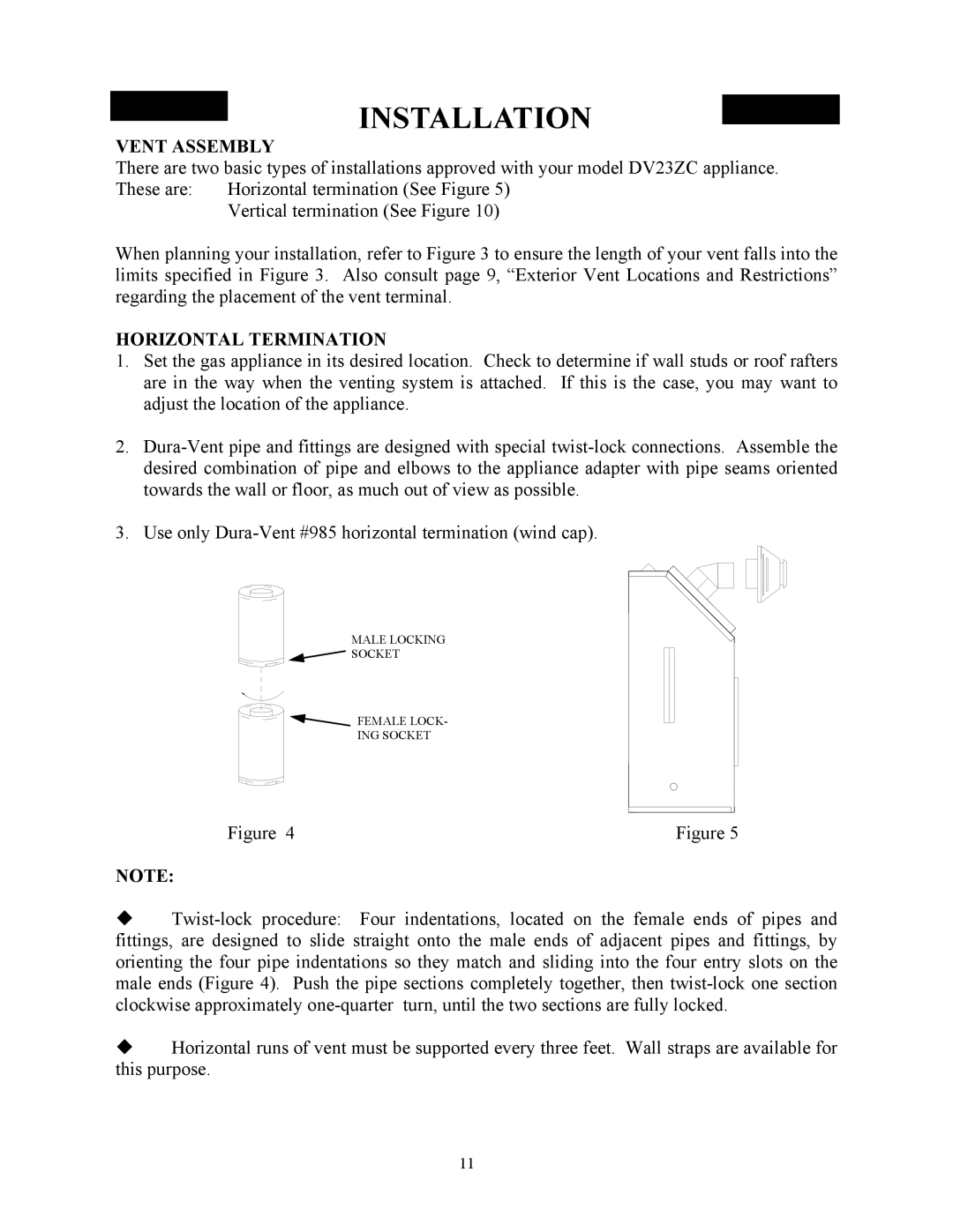
MALE LOCKING
![]() SOCKET
SOCKET
FEMALE LOCK-
ING SOCKET
Figure 4 | Figure 5 |
NOTE:
Horizontal runs of vent must be supported every three feet. Wall straps are available for this purpose.
11