INSTALLATION
HORIZONTAL TERMINATION (continued)
NOTE:
The horizontal run of vent must be level, or have a
A 2" clearance (airspace) MUST be maintained on all vent pipe.
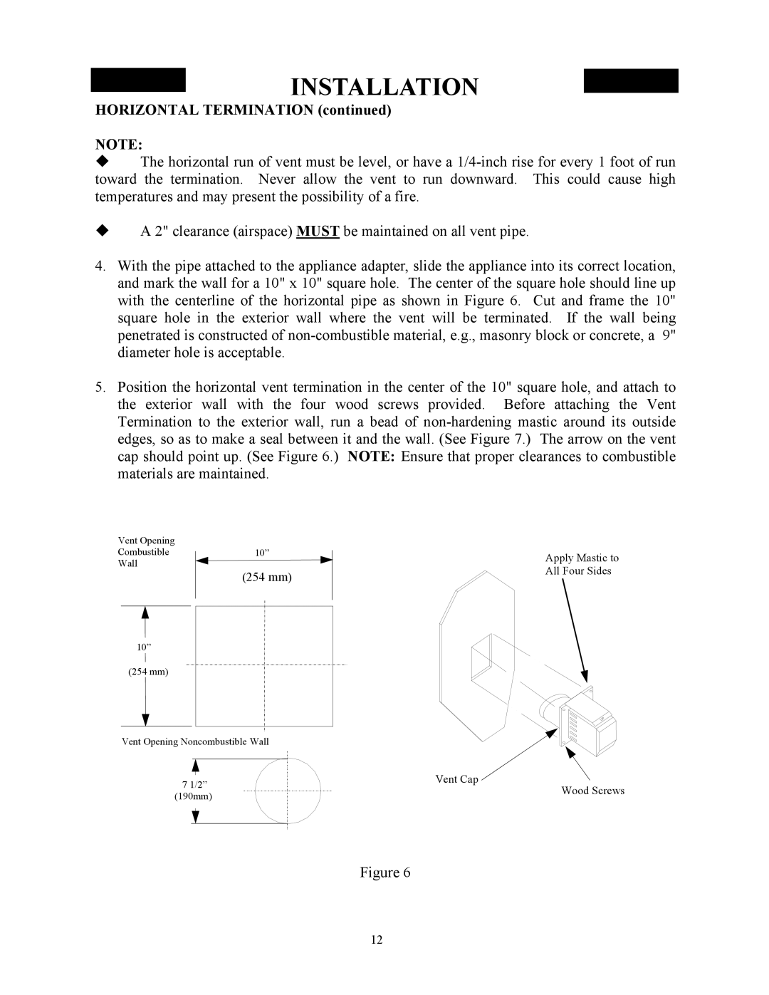
4.With the pipe attached to the appliance adapter, slide the appliance into its correct location, and mark the wall for a 10" x 10" square hole. The center of the square hole should line up with the centerline of the horizontal pipe as shown in Figure 6. Cut and frame the 10" square hole in the exterior wall where the vent will be terminated. If the wall being penetrated is constructed of
5.Position the horizontal vent termination in the center of the 10" square hole, and attach to the exterior wall with the four wood screws provided. Before attaching the Vent Termination to the exterior wall, run a bead of
Vent Opening
Combustible
Wall
10”
(254 mm)
10”
(254 mm)
Apply Mastic to All Four Sides
Vent Opening Noncombustible Wall
7 1/2” | Vent Cap | |
Wood Screws | ||
(190mm) | ||
|
Figure 6
12