5. PRINCIPLES OF WORK
5.1.The LRB 20000 assembly (Fig.1) consists of rangefinder 1 mounted on the angular mount 2. The latter is mounted on the tripod 3.
5.2.Rangefinder (Fig.2) is designed for terrain observation and measuring the distance to the closest or
The schematic circuit diagram of range finder (Fig.3) shows rechargeable battery (G1), controls switches (S1- S4), pumping and firing elements (ref. designations
Button switches S2 and S3 labeled (MEASURE 1) and (MEASURE L) respectively are used to prepare the rangefinder for taking a measurement (by pressing one of those buttons). Button S2 is operated to range the closest target, whereas button S3 is used to engage the
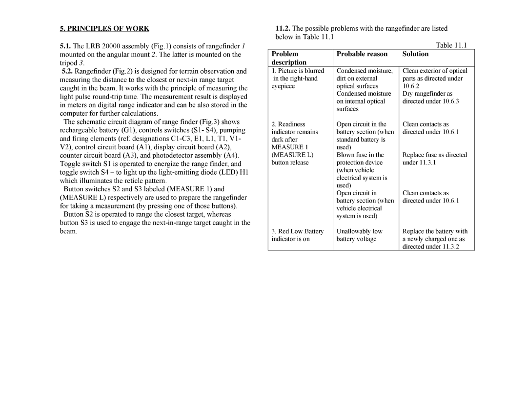
11.2.The possible problems with the rangefinder are listed below in Table 11.1
|
| Table 11.1 |
Problem | Probable reason | Solution |
description |
|
|
1. Picture is blurred | Condensed moisture, | Clean exterior of optical |
in the | dirt on external | parts as directed under |
eyepiece | optical surfaces | 10.6.2 |
| Condensed moisture | Dry rangefinder as |
| on internal optical | directed under 10.6.3 |
| surfaces |
|
2. Readiness | Open circuit in the | Clean contacts as |
indicator remains | battery section (when | directed under 10.6.1 |
dark after | standard battery is |
|
MEASURE 1 | used) | Replace fuse as directed |
(MEASURE L) | Blown fuse in the | |
button release | protection device | under 11.3.1 |
| (when vehicle |
|
| electrical system is |
|
| used) | Clean contacts as |
| Open circuit in | |
| battery section (when | directed under 10.6.1 |
| vehicle electrical |
|
| system is used) |
|
3. Red Low Battery | Unallowably low | Replace the battery with |
indicator is on | battery voltage | a newly charged one as |
|
| directed under 11.3.2 |
